

Configurar las interfaces de red SR-IOV para SAP HANA en SUSE KVM
 Sugerir cambios
Configura interfaces de red SR-IOV en SUSE KVM para SAP HANA. Configura funciones virtuales (VF), asígnalas a máquinas virtuales y configura conexiones de red redundantes para lograr un rendimiento óptimo y acceso al almacenamiento. También se admite la red en puente.
Paso 1: Configurar SR-IOV
Habilite y configure la funcionalidad SR-IOV en el firmware del adaptador para permitir la creación de funciones virtuales.
Este procedimiento se basa en "Portal de soporte empresarial de NVIDIA | Cómo configurar SR-IOV para ConnectX-4/ConnectX-5/ConnectX-6 con KVM (Ethernet)" . La guía SUSE SAP HANA KVM describe esto basándose en una NIC INTEL.
Se recomienda utilizar conexiones Ethernet redundantes combinando dos puertos físicos como enlace troncal/enlace. Los puertos virtuales (VF) asignados a la máquina virtual también deben estar configurados como troncales dentro de la máquina virtual.

Asegúrese de que se cumplan los siguientes requisitos previos:
-
KVM está instalado
-
SR-IOV está habilitado en la BIOS del servidor.
-
La transferencia directa de PCI se habilita agregando “intel_iommu=on” e “iommu=pt” como opción en el gestor de arranque.
-
Los controladores MLNX_OFED más recientes están instalados en los hosts KVM y en la máquina virtual.

|
Cada VF asignada a una VM requiere un ancho de banda de al menos 10 Gbit/s. No cree ni asigne más de dos VF para un puerto físico de 25GbE. |
-
Ejecutar MFT (Herramientas de firmware de Mellanox):
# mst start
Starting MST (Mellanox Software Tools) driver set
Loading MST PCI module – Success
Loading MST PCI configuration module – Success
Create devices
Unloading MST PCI module (unused) – Success
-
Localice el dispositivo:
# mst status
MST modules:
------------
MST PCI module is not loaded
MST PCI configuration module loaded

MST devices:

------------

/dev/mst/mt4125_pciconf0 - PCI configuration cycles access.
domain:bus:dev.fn=0000:ab:00.0 addr.reg=88 data.reg=92 cr_bar.gw_offset=-1

Chip revision is: 00
-
Compruebe el estado del dispositivo:
mlxconfig -d /dev/mst/mt4125_pciconf0 q |grep -e SRIOV_EN -e NUM_OF_VFS
NUM_OF_VFS 8
SRIOV_EN True(1)_
-
Si es necesario, habilite SR-IOV:
mlxconfig -d /dev/mst/mt4125_pciconf0 set SRIOV_EN=1
-
Establezca la cantidad máxima de VF:
mlxconfig -d /dev/mst/mt4125_pciconf0 set NUM_OF_VFS=4
-
Reinicie el servidor si fue necesario habilitar la función o si se cambió la cantidad máxima de VF.
Paso 2: Crear las interfaces virtuales
Cree funciones virtuales (VF) en los puertos de red físicos para habilitar la funcionalidad SR-IOV. En este paso, se crean cuatro VF por puerto físico.
-
Localiza el dispositivo:
# ibstat

CA 'mlx5_0'
CA type: MT4125
Number of ports: 1
Firmware version: 22.36.1010
Hardware version: 0
Node GUID: 0xa088c20300a6f6fc
System image GUID: 0xa088c20300a6f6fc
Port 1:
State: Active
Physical state: LinkUp
Rate: 100
Base lid: 0
LMC: 0
SM lid: 0
Capability mask: 0x00010000
Port GUID: 0xa288c2fffea6f6fd
Link layer: Ethernet
CA 'mlx5_1'
CA type: MT4125
Number of ports: 1
Firmware version: 22.36.1010
Hardware version: 0
Node GUID: 0xa088c20300a6f6fd
System image GUID: 0xa088c20300a6f6fc
Port 1:
State: Active
Physical state: LinkUp
Rate: 100
Base lid: 0
LMC: 0
SM lid: 0
Capability mask: 0x00010000
Port GUID: 0xa288c2fffea6f6fd
Link layer: Ethernet
Si se ha creado un vínculo, el resultado sería similar al siguiente:
# ibstat
CA 'mlx5_bond_0'
CA type: MT4125
Number of ports: 1
Firmware version: 22.36.1010
Hardware version: 0
Node GUID: 0xa088c20300a6f6fc
System image GUID: 0xa088c20300a6f6fc
Port 1:
State: Active
Physical state: LinkUp
Rate: 100
Base lid: 0
LMC: 0
SM lid: 0
Capability mask: 0x00010000
Port GUID: 0xa288c2fffea6f6fc
Link layer: Ethernet
#:/etc/sysconfig/network # cat /sys/class/infiniband/mlx5_bond_0/device/
aerdevcorrectable iommugroup/ resetmethod
aerdevfatal irq resource
aerdevnonfatal link/ resource0
arienabled localcpulist resource0wc
brokenparitystatus localcpus revision
class maxlinkspeed rom
config maxlinkwidth sriovdriversautoprobe
consistentdmamaskbits mlx5_core.eth.0/ sriovnumvfs
urrentlinkspeed mlx5_core.rdma.0/ sriovoffset
currentlinkwidth modalias sriovstride
d3coldallowed msibus sriovtotalvfs
device msiirqs/ sriovvfdevice
dmamaskbits net/ sriovvftotalmsix
driver/ numanode subsystem/
driveroverride pools subsystemdevice
enable power/ subsystemvendor
firmwarenode/ powerstate uevent
infiniband/ ptp/ vendor
infinibandmad/ remove vpd
infinibandverbs/ rescan
iommu/ reset
# ibdev2netdev
mlx5_0 port 1 ==> eth4 (Up)
mlx5_1 port 1 ==> eth5 (Up)
-
Obtenga el total de VF permitidos y configurados en el firmware:
# cat /sys/class/net/eth4/device/sriov_totalvfs
4
# cat /sys/class/net/eth5/device/sriov_totalvfs
4
-
Obtenga el número actual de VF en este dispositivo:
# cat /sys/class/infiniband/mlx5_0/device/sriov_numvfs
0
# cat /sys/class/infiniband/mlx5_1/device/sriov_numvfs
0
-
Establezca el número deseado de VF:
# echo 4 > /sys/class/infiniband/mlx5_0/device/sriov_numvfs
# echo 4 > /sys/class/infiniband/mlx5_1/device/sriov_numvfs
Si ya ha configurado un enlace utilizando estos dos puertos, el primer comando debe ejecutarse en dicho enlace:
# echo 4 > /sys/class/infiniband/mlx5_bond_0/device/sriov_numvfs
-
Compruebe el bus PCI:
# lspci -D | grep Mellanox

0000:ab:00.0 Ethernet controller: Mellanox Technologies MT2892 Family [ConnectX-6 Dx]
0000:ab:00.1 Ethernet controller: Mellanox Technologies MT2892 Family [ConnectX-6 Dx]
0000:ab:00.2 Ethernet controller: Mellanox Technologies ConnectX Family mlx5Gen Virtual Function
0000:ab:00.3 Ethernet controller: Mellanox Technologies ConnectX Family mlx5Gen Virtual Function
0000:ab:00.4 Ethernet controller: Mellanox Technologies ConnectX Family mlx5Gen Virtual Function
0000:ab:00.5 Ethernet controller: Mellanox Technologies ConnectX Family mlx5Gen Virtual Function
0000:ab:01.2 Ethernet controller: Mellanox Technologies ConnectX Family mlx5Gen Virtual Function
0000:ab:01.3 Ethernet controller: Mellanox Technologies ConnectX Family mlx5Gen Virtual Function
0000:ab:01.4 Ethernet controller: Mellanox Technologies ConnectX Family mlx5Gen Virtual Function
0000:ab:01.5 Ethernet controller: Mellanox Technologies ConnectX Family mlx5Gen Virtual Function
# ibdev2netdev -v

0000:ab:00.0 mlx5_0 (MT4125 - 51TF3A5000XV3) Mellanox ConnectX-6 Dx 100GbE QSFP56 2-port PCIe 4 Ethernet Adapter fw 22.36.1010 port 1 (ACTIVE) ==> eth4 (Up)
0000:ab:00.1 mlx5_1 (MT4125 - 51TF3A5000XV3) Mellanox ConnectX-6 Dx 100GbE QSFP56 2-port PCIe 4 Ethernet Adapter fw 22.36.1010 port 1 (ACTIVE) ==> eth6 (Up)
0000:ab:00.2 mlx523 (MT4126 - NA) fw 22.36.1010 port 1 (DOWN ) ==> eth6 (Down)
0000:ab:00.3 mlx5_3 (MT4126 - NA) fw 22.36.1010 port 1 (DOWN ) ==> eth7 (Down)
0000:ab:00.4 mlx5_4 (MT4126 - NA) fw 22.36.1010 port 1 (DOWN ) ==> eth8 (Down)
0000:ab:00.5 mlx5_5 (MT4126 - NA) fw 22.36.1010 port 1 (DOWN ) ==> eth9 (Down)
0000:ab:01.2 mlx5_6 (MT4126 - NA) fw 22.36.1010 port 1 (DOWN ) ==> eth10 (Down)
0000:ab:01.3 mlx5_7 (MT4126 - NA) fw 22.36.1010 port 1 (DOWN ) ==> eth11 (Down)
0000:ab:01.4 mlx5_8 (MT4126 - NA) fw 22.36.1010 port 1 (DOWN ) ==> eth12 (Down)
0000:ab:01.5 mlx5_9 (MT4126 - NA) fw 22.36.1010 port 1 (DOWN ) ==> eth13 (Down)
-
Compruebe la configuración de las VF mediante la herramienta IP:
# ip link show
…
6: eth4: <BROADCAST,MULTICAST,SLAVE,UP,LOWER_UP> mtu 9000 qdisc mq master bond0 state UP mode DEFAULT group default qlen 1000

link/ether a0:88:c2:a6:f6:fd brd ff:ff:ff:ff:ff:ff permaddr a0:88:c2:a6:f6:fc
vf 0 link/ether 00:00:00:00:00:00 brd ff:ff:ff:ff:ff:ff, spoof checking off, link-state auto, trust off, query_rss off
vf 1 link/ether 00:00:00:00:00:00 brd ff:ff:ff:ff:ff:ff, spoof checking off, link-state auto, trust off, query_rss off
vf 2 link/ether 00:00:00:00:00:00 brd ff:ff:ff:ff:ff:ff, spoof checking off, link-state auto, trust off, query_rss off
vf 3 link/ether 00:00:00:00:00:00 brd ff:ff:ff:ff:ff:ff, spoof checking off, link-state auto, trust off, query_rss off

altname enp171s0f0np0
altname ens3f0np0

7: eth5: <BROADCAST,MULTICAST,SLAVE,UP,LOWER_UP> mtu 9000 qdisc mq master bond0 state UP mode DEFAULT group default qlen 1000

link/ether a0:88:c2:a6:f6:fd brd ff:ff:ff:ff:ff:ff
vf 0 link/ether 00:00:00:00:00:00 brd ff:ff:ff:ff:ff:ff, spoof checking off, link-state auto, trust off, query_rss off
vf 1 link/ether 00:00:00:00:00:00 brd ff:ff:ff:ff:ff:ff, spoof checking off, link-state auto, trust off, query_rss off
vf 2 link/ether 00:00:00:00:00:00 brd ff:ff:ff:ff:ff:ff, spoof checking off, link-state auto, trust off, query_rss off
vf 3 link/ether 00:00:00:00:00:00 brd ff:ff:ff:ff:ff:ff, spoof checking off, link-state auto, trust off, query_rss off

altname enp171s0f1np1
altname ens3f1np1
…
Paso 3: Habilitar las VF durante el arranque
Configure los ajustes de VF para que persistan tras los reinicios del sistema mediante la creación de servicios systemd y scripts de inicio.
-
Crea un archivo de unidad systemd
/etc/systemd/system/after.localcon el siguiente contenido:[Unit] Description=/etc/init.d/after.local Compatibility After=libvirtd.service Requires=libvirtd.service [Service] Type=oneshot ExecStart=/etc/init.d/after.local RemainAfterExit=true [Install] WantedBy=multi-user.target
-
Crea el script /etc/init.d/after.local:
#! /bin/sh
#
#
# ...
echo 4 > /sys/class/infiniband/mlx5_bond_0/device/sriov_numvfs
echo 4 > /sys/class/infiniband/mlx5_1/device/sriov_numvfs
-
Asegúrese de que el archivo se pueda ejecutar:
# cd /etc/init.d/
# chmod 750 after.local
Paso 4: Asignar las interfaces virtuales a la máquina virtual
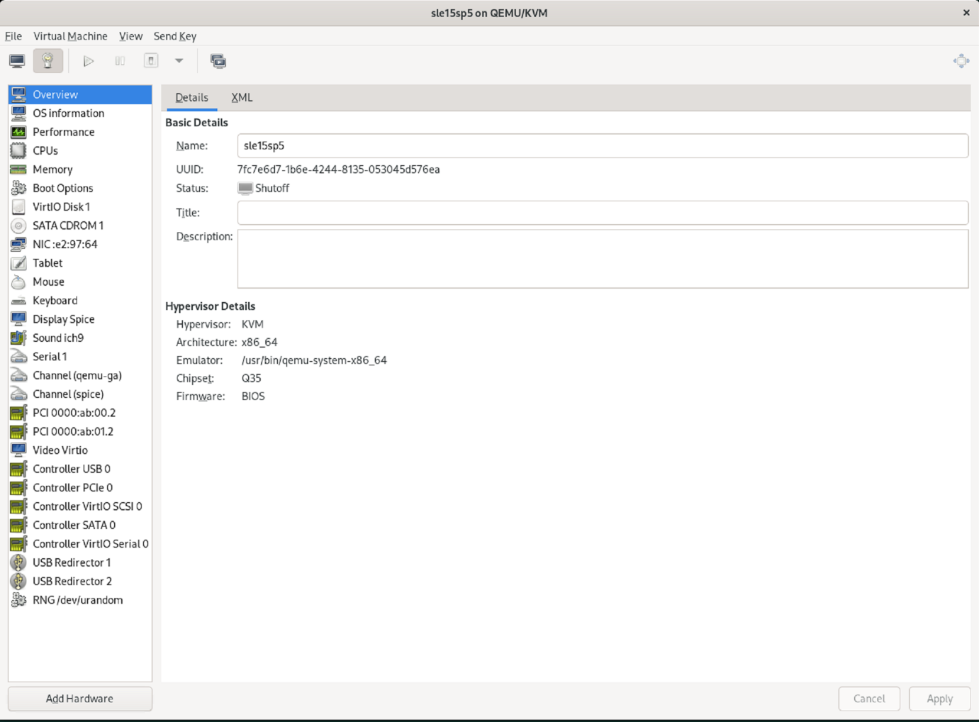
Asigne las funciones virtuales creadas a la máquina virtual SAP HANA como dispositivos host PCI mediante virt-manager.
-
Inicie virt-manager.

-
Abra la máquina virtual deseada.
-
Seleccione Agregar hardware. +
-
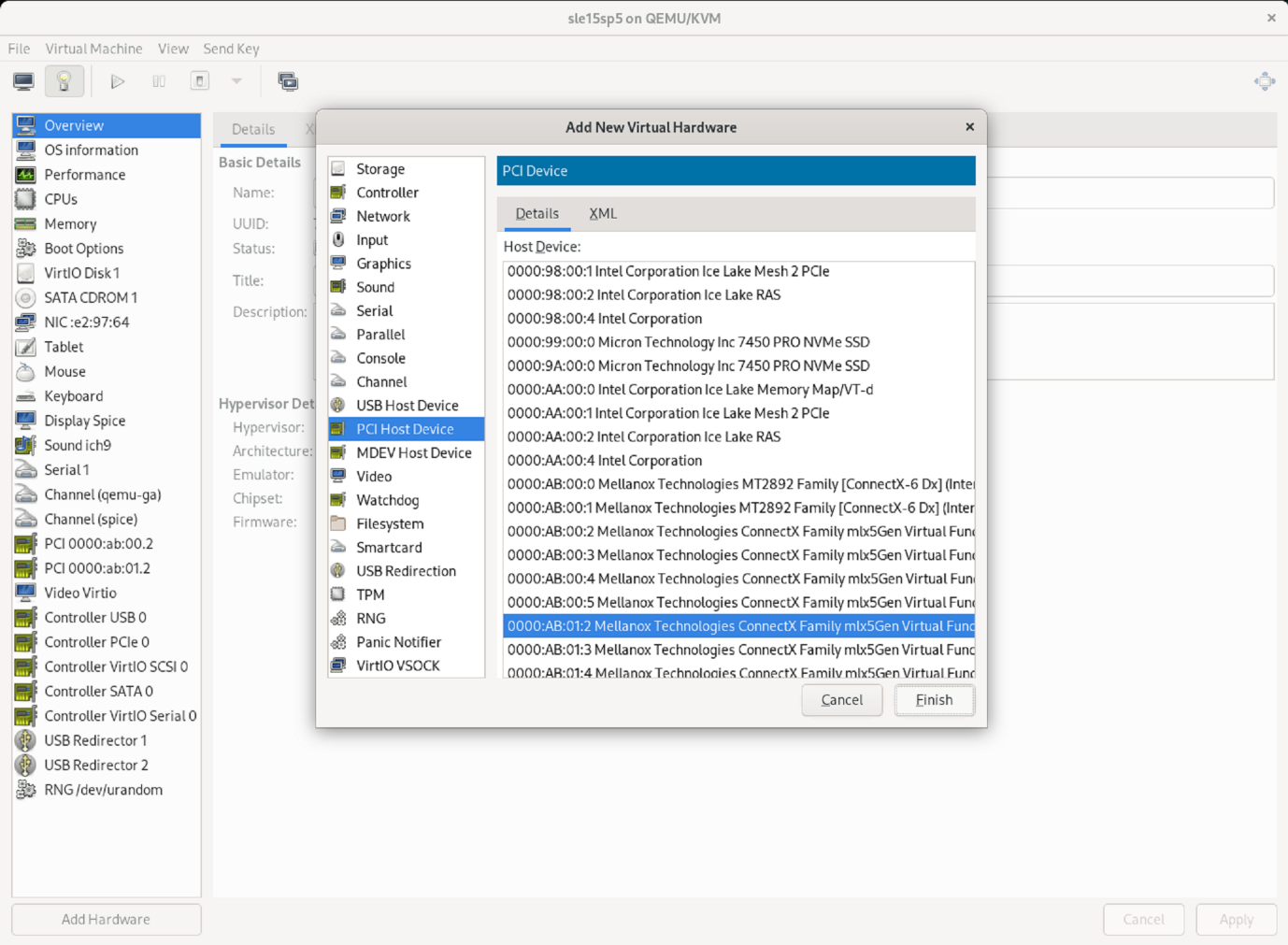
Elija la NIC virtual deseada del primer puerto físico de la lista de dispositivos host PCI y pulse Finalizar.
En este ejemplo, 0000.AB:00:2 - 0000.AB:00:4 pertenecen al primer puerto físico y 0000.AB:01:2 - 0000.AB:01:4 pertenecen al segundo puerto físico.

-
Elija el siguiente puerto NIC virtual de la lista de dispositivos host PCI, utilice un puerto virtual del segundo puerto físico y seleccione Finalizar.
-
Posteriormente, las interfaces virtuales se asignan a la máquina virtual y esta puede iniciarse. +

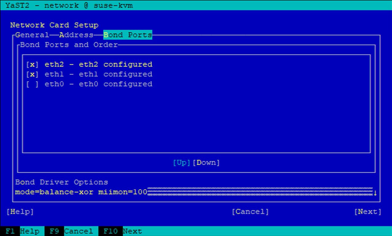
Paso 5: Configurar las interfaces de red dentro de la máquina virtual
Inicie sesión en la máquina virtual y configure las dos VF como enlace. Elija el modo 0 o el modo 2. No utilice LACP, ya que LACP solo se puede usar en puertos físicos. La figura siguiente muestra una configuración de modo 2 utilizando YAST.
¿Que sigue?
Una vez configuradas las interfaces de red SR-IOV,"Configurar redes Fibre Channel" si se va a utilizar FCP como protocolo de almacenamiento.