

古いCiscoスイッチからCisco Nexus 9336C-FX2 および 9336C-FX2-T スイッチに移行する
 変更を提案
変更を提案
古いCiscoクラスタ スイッチからCisco Nexus 9336C-FX2 および 9336C-FX2-T クラスタ ネットワーク スイッチへの中断のない移行を実行できます。
要件の確認
次のことを確認してください。
-
正しいスイッチが移行されたことを確認するために、スイッチのシリアル番号を確認しました。
-
Nexus 9336C-FX2 スイッチの一部のポートは、10GbE または 40GbE で動作するように構成されています。
-
ノードから Nexus 9336C-FX2 クラスタ スイッチへの 10GbE および 40GbE 接続が計画、移行、および文書化されました。
-
クラスターは完全に機能しています (ログにエラーや同様の問題は発生しないはずです)。
-
Cisco Nexus 9336C-FX2 スイッチの初期カスタマイズが完了し、次のようになりました。
-
9336C-FX2 スイッチは最新の推奨バージョンのソフトウェアを実行しています。
-
LIF を新しいスイッチに移行する前に、リファレンス コンフィギュレーション ファイル (RCF) が新しいスイッチに完全に適用されていることを確認します。
-
ネットワーク トラフィックを移行する前に、両方のスイッチの実行構成と起動構成を確認してください。
-
DNS、NTP、SMTP、SNMP、SSH などのサイトのカスタマイズはすべて新しいスイッチで構成されます。
-
-
スイッチの互換性表は、 "Ciscoイーサネット スイッチ"サポートされているONTAP、NX-OS、および RCF バージョンについては、ページをご覧ください。
-
Ciscoスイッチのアップグレードおよびダウングレード手順については、 Cisco Webサイトで入手可能な適切なソフトウェアおよびアップグレードガイドを確認してください。 "Cisco Nexus 9000 シリーズ スイッチのサポート"ページ。

|
AFF A800またはAFF C800システムで e0a および e1a クラスタ ポートのポート速度を変更する場合、速度変換後に不正なパケットが受信されることがあります。見る "バグ1570339"ナレッジベースの記事 "40GbEから100GbEへの変換後のT6ポートのCRCエラー"ガイダンスのため。 |
スイッチを移行する
この手順の例では、2つのノードを使用します。これらのノードは、2 つの 10GbE クラスター相互接続ポート e0a と e0b を使用します。参照 "Hardware Universe"プラットフォーム上の正しいクラスター ポートを確認します。見る "HWU にない機器をインストールするには、どのような追加情報が必要ですか?" スイッチのインストール要件の詳細については、こちらをご覧ください。
|
|
コマンド出力は、 ONTAPのリリースによって異なる場合があります。 |
この手順の例で使用するスイッチとノードの名前は次のとおりです。
-
既存の2つのCiscoスイッチの名前は*cs1*と*cs2*です。
-
新しい Nexus 9336C-FX2 クラスタ スイッチは cs1-new と cs2-new です。
-
ノード名は node1 と node2 です。
-
クラスター LIF 名は、ノード 1 の場合は node1_clus1 と node1_clus2、ノード 2 の場合は node2_clus1 と node2_clus2 です。
-
cluster1::>* プロンプトはクラスターの名前を示します。
この手順では、次の例を参照してください。
この手順では、 ONTAPコマンドと "Nexus 9000 シリーズ スイッチ"コマンド。特に明記されていない限り、 ONTAPコマンドが使用されます。
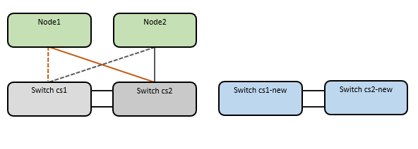
この手順では、次のシナリオについて説明します。
-
まず、スイッチ cs2 をスイッチ cs2-new に置き換えます。
-
クラスター ノードへのポートをシャットダウンします。クラスターの不安定性を回避するには、すべてのポートを同時にシャットダウンする必要があります。
-
すべてのクラスタ LIF は新しいスイッチ cs2-new にフェイルオーバーします。
-
-
次に、ノードと cs2 間のケーブルが cs2 から切断され、cs2-new に再接続されます。
-
-
スイッチ cs1 はスイッチ cs1-new に置き換えられます。
-
クラスター ノードへのポートをシャットダウンします。クラスターの不安定性を回避するには、すべてのポートを同時にシャットダウンする必要があります。
-
すべてのクラスタ LIF が新しいスイッチ cs1-new にフェイルオーバーします。
-
-
次に、ノードと cs1 間のケーブルが cs1 から切断され、cs1-new に再接続されます。
-
|
|
この手順では、動作中のスイッチ間リンク (ISL) は必要ありません。これは、RCF バージョンの変更によって ISL 接続が一時的に影響を受ける可能性があるため、設計によるものです。クラスタ操作が中断されないようにするには、次の手順で、ターゲット スイッチで手順を実行しながら、すべてのクラスタ LIF を動作中のパートナー スイッチにフェイルオーバーします。 |
ステップ1: 移行の準備
-
このクラスタでAutoSupportが有効になっている場合は、 AutoSupportメッセージを呼び出して自動ケース作成を抑制します。
system node autosupport invoke -node * -type all -message MAINT=xhここで、x はメンテナンス ウィンドウの期間 (時間単位) です。
AutoSupportメッセージはテクニカル サポートにこのメンテナンス タスクについて通知し、メンテナンス時間中はケースの自動作成が停止されます。 -
続行するかどうかを尋ねられたら y と入力して、権限レベルを「advanced」に変更します。
set -privilege advancedadvancedのプロンプト(*>)が表示されます。
ステップ2: ポートとケーブルを構成する
-
新しいスイッチで、スイッチ cs1-new と cs2-new 間の ISL がケーブル接続され、正常であることを確認します。
show port-channel summary例を表示
cs1-new# show port-channel summary Flags: D - Down P - Up in port-channel (members) I - Individual H - Hot-standby (LACP only) s - Suspended r - Module-removed b - BFD Session Wait S - Switched R - Routed U - Up (port-channel) p - Up in delay-lacp mode (member) M - Not in use. Min-links not met -------------------------------------------------------------------------------- Group Port- Type Protocol Member Ports Channel -------------------------------------------------------------------------------- 1 Po1(SU) Eth LACP Eth1/35(P) Eth1/36(P) cs2-new# show port-channel summary Flags: D - Down P - Up in port-channel (members) I - Individual H - Hot-standby (LACP only) s - Suspended r - Module-removed b - BFD Session Wait S - Switched R - Routed U - Up (port-channel) p - Up in delay-lacp mode (member) M - Not in use. Min-links not met -------------------------------------------------------------------------------- Group Port- Type Protocol Member Ports Channel -------------------------------------------------------------------------------- 1 Po1(SU) Eth LACP Eth1/35(P) Eth1/36(P) -
既存のクラスター スイッチに接続されている各ノード上のクラスター ポートを表示します。
network device-discovery show例を表示
cluster1::*> network device-discovery show -protocol cdp Node/ Local Discovered Protocol Port Device (LLDP: ChassisID) Interface Platform ----------- ------ ------------------------- ---------------- ---------------- node1 /cdp e0a cs1 Ethernet1/1 N5K-C5596UP e0b cs2 Ethernet1/2 N5K-C5596UP node2 /cdp e0a cs1 Ethernet1/1 N5K-C5596UP e0b cs2 Ethernet1/2 N5K-C5596UP -
各クラスタ ポートの管理ステータスまたは動作ステータスを決定します。
-
すべてのクラスター ポートが正常な状態で稼働していることを確認します。
network port show -ipspace Cluster例を表示
cluster1::*> network port show -ipspace Cluster Node: node1 Ignore Speed(Mbps) Health Health Port IPspace Broadcast Domain Link MTU Admin/Oper Status Status --------- ------------ ---------------- ---- ---- ----------- -------- ------ e0a Cluster Cluster up 9000 auto/10000 healthy false e0b Cluster Cluster up 9000 auto/10000 healthy false Node: node2 Ignore Speed(Mbps) Health Health Port IPspace Broadcast Domain Link MTU Admin/Oper Status Status --------- ------------ ---------------- ---- ---- ----------- -------- ------ e0a Cluster Cluster up 9000 auto/10000 healthy false e0b Cluster Cluster up 9000 auto/10000 healthy false -
すべてのクラスタ インターフェイス (LIF) がホーム ポート上にあることを確認します。
network interface show -vserver Cluster例を表示
cluster1::*> network interface show -vserver Cluster Logical Status Network Current Current Is Vserver Interface Admin/Oper Address/Mask Node Port Home ----------- ----------- ---------- ------------------ ----------- ------- ---- Cluster node1_clus1 up/up 169.254.209.69/16 node1 e0a true node1_clus2 up/up 169.254.49.125/16 node1 e0b true node2_clus1 up/up 169.254.47.194/16 node2 e0a true node2_clus2 up/up 169.254.19.183/16 node2 e0b true -
クラスターが両方のクラスター スイッチの情報を表示することを確認します。
system cluster-switch show -is-monitoring-enabled-operational true
例を表示
cluster1::*> system cluster-switch show -is-monitoring-enabled-operational true Switch Type Address Model --------------------------- ------------------ ---------------- --------------- cs1 cluster-network 10.233.205.92 N5K-C5596UP Serial Number: FOXXXXXXXGS Is Monitored: true Reason: None Software Version: Cisco Nexus Operating System (NX-OS) Software, Version 9.3(4) Version Source: CDP cs2 cluster-network 10.233.205.93 N5K-C5596UP Serial Number: FOXXXXXXXGD Is Monitored: true Reason: None Software Version: Cisco Nexus Operating System (NX-OS) Software, Version 9.3(4) Version Source: CDP -
-
この手順の自動復帰を無効にすると、クラスター LIF は自動的にホーム ポートに戻りません。現在のポートが稼働し続けている限り、それらは現在のポート上に残ります。
network interface modify -vserver Cluster -lif * -auto-revert false
自動リバートを無効にすると、後でスイッチ ポートがシャットダウンされたときに、 ONTAP はクラスタ LIF のみをフェイルオーバーするようになります。 -
クラスタ スイッチ cs2 で、クラスタ LIF をフェイルオーバーするために、すべてのノードのクラスタ ポートに接続されているポートをシャットダウンします。
cs2# configure
cs2(config)# interface eth1/1-1/2
cs2(config-if-range)# shutdown
cs2(config-if-range)# exit
cs2(config)# exit
cs2#
-
クラスタ LIF がクラスタ スイッチ cs1 でホストされているポートにフェイルオーバーされたことを確認します。数秒かかる場合があります。
network interface show -vserver Cluster例を表示
cluster1::*> network interface show -vserver Cluster Logical Status Network Current Current Is Vserver Interface Admin/Oper Address/Mask Node Port Home ----------- ------------- ---------- ------------------ ---------- ------- ---- Cluster node1_clus1 up/up 169.254.3.4/16 node1 e0a true node1_clus2 up/up 169.254.3.5/16 node1 e0a false node2_clus1 up/up 169.254.3.8/16 node2 e0a true node2_clus2 up/up 169.254.3.9/16 node2 e0a false -
クラスタが正常に動作していることを確認します。
cluster show例を表示
cluster1::*> cluster show
Node       Health  Eligibility   Epsilon
---------- ------- ------------- -------
node1      true    true          false
node2      true    true          false
-
クラスタLIFがスイッチcs1にフェイルオーバーし、クラスタが正常である場合は、ステップ。10 。一部のクラスタ LIF が正常でないか、クラスタが正常でない場合は、次のようにスイッチ cs2 への接続をロールバックできます。
-
すべてのノードのクラスター ポートに接続されているポートを起動します。
cs2# configure
cs2(config)# interface eth1/1-1/2
cs2(config-if-range)# no shutdown
cs2(config-if-range)# exit
cs2(config)# exit
cs2#
-
クラスタ LIF がクラスタ スイッチ cs1 でホストされているポートにフェイルオーバーされたことを確認します。数秒かかる場合があります。
network interface show -vserver Cluster例を表示
cluster1::*> network interface show -vserver Cluster Logical Status Network Current Current Is Vserver Interface Admin/Oper Address/Mask Node Port Home ----------- ------------- ---------- ------------------ ---------- ------- ---- Cluster node1_clus1 up/up 169.254.3.4/16 node1 e0a true node1_clus2 up/up 169.254.3.5/16 node1 e0a false node2_clus1 up/up 169.254.3.8/16 node2 e0a true node2_clus2 up/up 169.254.3.9/16 node2 e0a false -
クラスタが正常に動作していることを確認します。
cluster show
例を表示
cluster1::*> cluster show
Node       Health  Eligibility   Epsilon
---------- ------- ------------- -------
node1      true    true          false
node2      true    true          false
-
-
LIFとクラスタのヘルスを回復したら、プロセスを再開します。ステップ。4 。
-
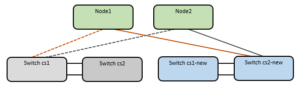
すべてのクラスタノード接続ケーブルを古い cs2 スイッチから新しい cs2-new スイッチに移動します。
クラスタノード接続ケーブルをcs2-newスイッチに移動
-
cs2-new に移動されたネットワーク接続の健全性を確認します。
network port show -ipspace Cluster例を表示
cluster1::*> network port show -ipspace Cluster

Node: node1
                                                                       Ignore
                                                  Speed(Mbps) Health   Health
Port      IPspace      Broadcast Domain Link MTU  Admin/Oper  Status   Status
--------- ------------ ---------------- ---- ---- ----------- -------- ------
e0a       Cluster      Cluster          up   9000  auto/10000 healthy  false
e0b       Cluster      Cluster          up   9000  auto/10000 healthy  false

Node: node2
                                                                       Ignore
                                                  Speed(Mbps) Health   Health
Port      IPspace      Broadcast Domain Link MTU  Admin/Oper  Status   Status
--------- ------------ ---------------- ---- ---- ----------- -------- ------
e0a       Cluster      Cluster          up   9000  auto/10000 healthy  false
e0b       Cluster      Cluster          up   9000  auto/10000 healthy  false
移動されたすべてのクラスター ポートが稼働している必要があります。
-
クラスター ポートのネイバー情報を確認します。
network device-discovery show -protocol cdp例を表示
cluster1::*> network device-discovery show -protocol cdp

Node/       Local  Discovered
Protocol    Port   Device (LLDP: ChassisID)  Interface      Platform
----------- ------ ------------------------- -------------  --------------
node1      /cdp
            e0a    cs1                       Ethernet1/1    N5K-C5596UP
            e0b    cs2-new                   Ethernet1/1/1  N9K-C9336C-FX2

node2      /cdp
            e0a    cs1                       Ethernet1/2    N5K-C5596UP
            e0b    cs2-new                   Ethernet1/1/2  N9K-C9336C-FX2
移動したクラスタ ポートが cs2-new スイッチをネイバーとして認識していることを確認します。
-
スイッチ cs2-new の観点からスイッチ ポートの接続を確認します。
cs2-new# show interface brief
cs2-new# show cdp neighbors
-
クラスタ スイッチ cs1 で、クラスタ LIF をフェイルオーバーするために、すべてのノードのクラスタ ポートに接続されているポートをシャットダウンします。
cs1# configure
cs1(config)# interface eth1/1-1/2
cs1(config-if-range)# shutdown
cs1(config-if-range)# exit
cs1(config)# exit
cs1#
すべてのクラスタ LIF は cs2-new スイッチにフェイルオーバーします。
-
クラスタ LIF がスイッチ cs2-new でホストされているポートにフェイルオーバーされたことを確認します。これには数秒かかる場合があります。
network interface show -vserver Cluster例を表示
cluster1::*> network interface show -vserver Cluster Logical Status Network Current Current Is Vserver Interfac Admin/Oper Address/Mask Node Port Home ----------- ------------ ---------- ------------------ ----------- ------- ---- Cluster node1_clus1 up/up 169.254.3.4/16 node1 e0b false node1_clus2 up/up 169.254.3.5/16 node1 e0b true node2_clus1 up/up 169.254.3.8/16 node2 e0b false node2_clus2 up/up 169.254.3.9/16 node2 e0b true -
クラスタが正常に動作していることを確認します。
cluster show例を表示
cluster1::*> cluster show
Node       Health  Eligibility   Epsilon
---------- ------- ------------- -------
node1      true    true          false
node2      true    true          false
-
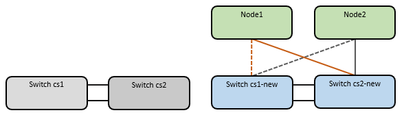
クラスタ ノード接続ケーブルを cs1 から新しい cs1-new スイッチに移動します。
クラスタノード接続ケーブルをcs1-newスイッチに移動
-
cs1-new に移動されたネットワーク接続の健全性を確認します。
network port show -ipspace Cluster例を表示
cluster1::*> network port show -ipspace Cluster

Node: node1
                                                                       Ignore
                                                  Speed(Mbps) Health   Health
Port      IPspace      Broadcast Domain Link MTU  Admin/Oper  Status   Status
--------- ------------ ---------------- ---- ---- ----------- -------- ------
e0a       Cluster      Cluster          up   9000  auto/10000 healthy  false
e0b       Cluster      Cluster          up   9000  auto/10000 healthy  false

Node: node2
                                                                       Ignore
                                                  Speed(Mbps) Health   Health
Port      IPspace      Broadcast Domain Link MTU  Admin/Oper  Status   Status
--------- ------------ ---------------- ---- ---- ----------- -------- ------
e0a       Cluster      Cluster          up   9000  auto/10000 healthy  false
e0b       Cluster      Cluster          up   9000  auto/10000 healthy  false
移動されたすべてのクラスター ポートが稼働している必要があります。
-
クラスター ポートのネイバー情報を確認します。
network device-discovery show例を表示
cluster1::*> network device-discovery show -protocol cdp
Node/       Local  Discovered
Protocol    Port   Device (LLDP: ChassisID)  Interface       Platform
----------- ------ ------------------------- --------------  --------------
node1      /cdp
            e0a    cs1-new                   Ethernet1/1/1   N9K-C9336C-FX2
            e0b    cs2-new                   Ethernet1/1/2   N9K-C9336C-FX2

node2      /cdp
            e0a    cs1-new                   Ethernet1/1/1   N9K-C9336C-FX2
            e0b    cs2-new                   Ethernet1/1/2   N9K-C9336C-FX2
移動したクラスタ ポートが cs1-new スイッチをネイバーとして認識していることを確認します。
-
スイッチ cs1-new の観点からスイッチ ポートの接続を確認します。
cs1-new# show interface brief
cs1-new# show cdp neighbors
-
cs1-new と cs2-new 間の ISL がまだ動作していることを確認します。
show port-channel summary例を表示
cs1-new# show port-channel summary
Flags:  D - Down        P - Up in port-channel (members)
        I - Individual  H - Hot-standby (LACP only)
        s - Suspended   r - Module-removed
        b - BFD Session Wait
        S - Switched    R - Routed
        U - Up (port-channel)
        p - Up in delay-lacp mode (member)
        M - Not in use. Min-links not met
--------------------------------------------------------------------------------
Group Port-       Type     Protocol  Member Ports
      Channel
--------------------------------------------------------------------------------
1     Po1(SU)     Eth      LACP      Eth1/35(P)   Eth1/36(P)

cs2-new# show port-channel summary
Flags:  D - Down        P - Up in port-channel (members)
        I - Individual  H - Hot-standby (LACP only)
        s - Suspended   r - Module-removed
        b - BFD Session Wait
        S - Switched    R - Routed
        U - Up (port-channel)
        p - Up in delay-lacp mode (member)
        M - Not in use. Min-links not met
--------------------------------------------------------------------------------
Group Port-       Type     Protocol  Member Ports
      Channel
--------------------------------------------------------------------------------
1     Po1(SU)     Eth      LACP      Eth1/35(P)   Eth1/36(P)
ステップ3: 構成を確認する
-
クラスタLIFで自動リバートを有効にします。
network interface modify -vserver Cluster -lif * -auto-revert true -
スイッチ cs2 で、すべてのクラスタ ポートをシャットダウンして再起動し、ホーム ポートにないすべてのクラスタ LIF の自動復帰をトリガーします。
cs2> enable
cs2# configure
cs2(config)# interface eth1/1-1/2
cs2(config-if-range)# shutdown

(Wait for 5-10 seconds before re-enabling the ports)

cs2(config-if-range)# no shutdown

(After executing the no shutdown command, the nodes detect the change and begin to auto-revert the cluster LIFs to their home ports)

cs2(config-if-range)# exit
cs2(config)# exit
cs2#
-
クラスタ LIF がホーム ポートに戻ったことを確認します (これには 1 分ほどかかる場合があります)。
network interface show -vserver Clusterいずれかのクラスタ LIF がホーム ポートに戻っていない場合は、手動で戻します。LIF を所有するローカル ノードの各ノード管理 LIF またはSP/ BMCシステム コンソールに接続する必要があります。
network interface revert -vserver Cluster -lif * -
クラスタが正常に動作していることを確認します。
cluster show -
リモート クラスタ インターフェイスの接続を確認します。
使用することができます `network interface check cluster-connectivity`クラスター接続のアクセシビリティ チェックを開始し、詳細を表示するコマンド:
network interface check cluster-connectivity start`そして `network interface check cluster-connectivity show
cluster1::*> network interface check cluster-connectivity start
|
|
実行する前に数秒待ってください `show`詳細を表示するコマンド。 |
cluster1::*> network interface check cluster-connectivity show
                                  Source          Destination       Packet
Node   Date                       LIF             LIF               Loss
------ -------------------------- --------------- ----------------- -----------
node1
       3/5/2022 19:21:18 -06:00   node1_clus2      node2_clus1      none
       3/5/2022 19:21:20 -06:00   node1_clus2      node2_clus2      none

node2
       3/5/2022 19:21:18 -06:00   node2_clus2      node1_clus1      none
       3/5/2022 19:21:20 -06:00   node2_clus2      node1_clus2      none
すべてのONTAPリリースでは、 `cluster ping-cluster -node <name>`接続を確認するコマンド:
cluster ping-cluster -node <name>
cluster1::*> cluster ping-cluster -node node2
Host is node2
Getting addresses from network interface table...
Cluster node1_clus1 169.254.209.69 node1     e0a
Cluster node1_clus2 169.254.49.125 node1     e0b
Cluster node2_clus1 169.254.47.194 node2     e0a
Cluster node2_clus2 169.254.19.183 node2     e0b
Local = 169.254.47.194 169.254.19.183
Remote = 169.254.209.69 169.254.49.125
Cluster Vserver Id = 4294967293
Ping status:

Basic connectivity succeeds on 4 path(s)
Basic connectivity fails on 0 path(s)
................
Detected 9000 byte MTU on 4 path(s):
    Local 169.254.19.183 to Remote 169.254.209.69
    Local 169.254.19.183 to Remote 169.254.49.125
    Local 169.254.47.194 to Remote 169.254.209.69
    Local 169.254.47.194 to Remote 169.254.49.125
Larger than PMTU communication succeeds on 4 path(s)
RPC status:
2 paths up, 0 paths down (tcp check)
2 paths up, 0 paths down (udp check)
スイッチを移行したら、"スイッチのヘルスモニタリングを設定する" 。