

SUSE KVM에서 SAP HANA에 대한 SR-IOV 네트워크 인터페이스 구성
 변경 제안
변경 제안
SAP HANA용 SUSE KVM에서 SR-IOV 네트워크 인터페이스를 구성합니다. 가상 함수(VF)를 설정하고, 이를 VM에 할당하고, 최적의 성능과 스토리지 액세스를 위한 이중화 네트워크 연결을 구성합니다. 브리지 네트워킹도 지원됩니다.
1단계: SR-IOV 설정
어댑터 펌웨어에서 SR-IOV 기능을 활성화하고 구성하여 가상 기능 생성을 허용합니다.
이 절차는 다음을 기반으로 합니다. "NVIDIA Enterprise 지원 포털 | KVM(이더넷)을 사용하여 ConnectX-4/ConnectX-5/ConnectX-6에 대한 SR-IOV 구성 방법" . SUSE SAP HANA KVM 가이드에서는 INTEL NIC를 기준으로 이를 설명합니다.
두 개의 물리적 포트를 트렁크/본드로 결합하여 중복 이더넷 연결을 사용하는 것이 좋습니다. VM에 할당된 가상 포트(VF)도 VM 내에서 트렁킹되어야 합니다.

다음 전제 조건이 충족되었는지 확인하세요.
-
KVM이 설치되었습니다
-
SR-IOV는 서버 BIOS에서 활성화됩니다.
-
부트로더에서 "intel_iommu=on" 및 "iommu=pt"를 옵션으로 추가하여 PCI 패스스루를 활성화합니다.
-
최신 MLNX_OFED 드라이버는 KVM 호스트와 VM에 설치됩니다.

|
VM에 할당된 각 VF에는 최소 10Gbit/s 대역폭이 필요합니다. 25GbE 물리적 포트에 대해 두 개 이상의 VF를 생성하고 할당하지 마세요. |
-
MFT(Mellanox 펌웨어 도구)를 실행합니다.
# mst start
Starting MST (Mellanox Software Tools) driver set
Loading MST PCI module – Success
Loading MST PCI configuration module – Success
Create devices
Unloading MST PCI module (unused) – Success
-
장치를 찾으세요:
# mst status
MST modules:
------------
MST PCI module is not loaded
MST PCI configuration module loaded

MST devices:

------------

/dev/mst/mt4125_pciconf0 - PCI configuration cycles access.
domain:bus:dev.fn=0000:ab:00.0 addr.reg=88 data.reg=92 cr_bar.gw_offset=-1

Chip revision is: 00
-
장치 상태를 확인하세요:
mlxconfig -d /dev/mst/mt4125_pciconf0 q |grep -e SRIOV_EN -e NUM_OF_VFS
NUM_OF_VFS 8
SRIOV_EN True(1)_
-
필요한 경우 SR-IOV를 활성화합니다.
mlxconfig -d /dev/mst/mt4125_pciconf0 set SRIOV_EN=1
-
VF의 최대 수를 설정합니다.
mlxconfig -d /dev/mst/mt4125_pciconf0 set NUM_OF_VFS=4
-
해당 기능을 활성화해야 하거나 최대 VF 수가 변경된 경우 서버를 재부팅하세요.
2단계: 가상 인터페이스 만들기
SR-IOV 기능을 활성화하려면 물리적 네트워크 포트에 가상 기능(VF)을 만듭니다. 이 단계에서는 물리적 포트당 4개의 VF가 생성됩니다.
-
장치를 찾으세요:
# ibstat

CA 'mlx5_0'
CA type: MT4125
Number of ports: 1
Firmware version: 22.36.1010
Hardware version: 0
Node GUID: 0xa088c20300a6f6fc
System image GUID: 0xa088c20300a6f6fc
Port 1:
State: Active
Physical state: LinkUp
Rate: 100
Base lid: 0
LMC: 0
SM lid: 0
Capability mask: 0x00010000
Port GUID: 0xa288c2fffea6f6fd
Link layer: Ethernet
CA 'mlx5_1'
CA type: MT4125
Number of ports: 1
Firmware version: 22.36.1010
Hardware version: 0
Node GUID: 0xa088c20300a6f6fd
System image GUID: 0xa088c20300a6f6fc
Port 1:
State: Active
Physical state: LinkUp
Rate: 100
Base lid: 0
LMC: 0
SM lid: 0
Capability mask: 0x00010000
Port GUID: 0xa288c2fffea6f6fd
Link layer: Ethernet
결합이 생성된 경우 출력은 다음과 같습니다.
# ibstat
CA 'mlx5_bond_0'
CA type: MT4125
Number of ports: 1
Firmware version: 22.36.1010
Hardware version: 0
Node GUID: 0xa088c20300a6f6fc
System image GUID: 0xa088c20300a6f6fc
Port 1:
State: Active
Physical state: LinkUp
Rate: 100
Base lid: 0
LMC: 0
SM lid: 0
Capability mask: 0x00010000
Port GUID: 0xa288c2fffea6f6fc
Link layer: Ethernet
#:/etc/sysconfig/network # cat /sys/class/infiniband/mlx5_bond_0/device/
aerdevcorrectable iommugroup/ resetmethod
aerdevfatal irq resource
aerdevnonfatal link/ resource0
arienabled localcpulist resource0wc
brokenparitystatus localcpus revision
class maxlinkspeed rom
config maxlinkwidth sriovdriversautoprobe
consistentdmamaskbits mlx5_core.eth.0/ sriovnumvfs
urrentlinkspeed mlx5_core.rdma.0/ sriovoffset
currentlinkwidth modalias sriovstride
d3coldallowed msibus sriovtotalvfs
device msiirqs/ sriovvfdevice
dmamaskbits net/ sriovvftotalmsix
driver/ numanode subsystem/
driveroverride pools subsystemdevice
enable power/ subsystemvendor
firmwarenode/ powerstate uevent
infiniband/ ptp/ vendor
infinibandmad/ remove vpd
infinibandverbs/ rescan
iommu/ reset
# ibdev2netdev
mlx5_0 port 1 ==> eth4 (Up)
mlx5_1 port 1 ==> eth5 (Up)
-
펌웨어에서 허용되고 구성된 총 VF를 가져옵니다.
# cat /sys/class/net/eth4/device/sriov_totalvfs
4
# cat /sys/class/net/eth5/device/sriov_totalvfs
4
-
이 장치의 현재 VF 수를 가져옵니다.
# cat /sys/class/infiniband/mlx5_0/device/sriov_numvfs
0
# cat /sys/class/infiniband/mlx5_1/device/sriov_numvfs
0
-
원하는 VF 수를 설정하세요:
# echo 4 > /sys/class/infiniband/mlx5_0/device/sriov_numvfs
# echo 4 > /sys/class/infiniband/mlx5_1/device/sriov_numvfs
이미 이 두 포트를 사용하여 본드를 구성한 경우 본드에 대해 첫 번째 명령을 실행해야 합니다.
# echo 4 > /sys/class/infiniband/mlx5_bond_0/device/sriov_numvfs
-
PCI 버스를 확인하세요:
# lspci -D | grep Mellanox

0000:ab:00.0 Ethernet controller: Mellanox Technologies MT2892 Family [ConnectX-6 Dx]
0000:ab:00.1 Ethernet controller: Mellanox Technologies MT2892 Family [ConnectX-6 Dx]
0000:ab:00.2 Ethernet controller: Mellanox Technologies ConnectX Family mlx5Gen Virtual Function
0000:ab:00.3 Ethernet controller: Mellanox Technologies ConnectX Family mlx5Gen Virtual Function
0000:ab:00.4 Ethernet controller: Mellanox Technologies ConnectX Family mlx5Gen Virtual Function
0000:ab:00.5 Ethernet controller: Mellanox Technologies ConnectX Family mlx5Gen Virtual Function
0000:ab:01.2 Ethernet controller: Mellanox Technologies ConnectX Family mlx5Gen Virtual Function
0000:ab:01.3 Ethernet controller: Mellanox Technologies ConnectX Family mlx5Gen Virtual Function
0000:ab:01.4 Ethernet controller: Mellanox Technologies ConnectX Family mlx5Gen Virtual Function
0000:ab:01.5 Ethernet controller: Mellanox Technologies ConnectX Family mlx5Gen Virtual Function
# ibdev2netdev -v

0000:ab:00.0 mlx5_0 (MT4125 - 51TF3A5000XV3) Mellanox ConnectX-6 Dx 100GbE QSFP56 2-port PCIe 4 Ethernet Adapter fw 22.36.1010 port 1 (ACTIVE) ==> eth4 (Up)
0000:ab:00.1 mlx5_1 (MT4125 - 51TF3A5000XV3) Mellanox ConnectX-6 Dx 100GbE QSFP56 2-port PCIe 4 Ethernet Adapter fw 22.36.1010 port 1 (ACTIVE) ==> eth6 (Up)
0000:ab:00.2 mlx523 (MT4126 - NA) fw 22.36.1010 port 1 (DOWN ) ==> eth6 (Down)
0000:ab:00.3 mlx5_3 (MT4126 - NA) fw 22.36.1010 port 1 (DOWN ) ==> eth7 (Down)
0000:ab:00.4 mlx5_4 (MT4126 - NA) fw 22.36.1010 port 1 (DOWN ) ==> eth8 (Down)
0000:ab:00.5 mlx5_5 (MT4126 - NA) fw 22.36.1010 port 1 (DOWN ) ==> eth9 (Down)
0000:ab:01.2 mlx5_6 (MT4126 - NA) fw 22.36.1010 port 1 (DOWN ) ==> eth10 (Down)
0000:ab:01.3 mlx5_7 (MT4126 - NA) fw 22.36.1010 port 1 (DOWN ) ==> eth11 (Down)
0000:ab:01.4 mlx5_8 (MT4126 - NA) fw 22.36.1010 port 1 (DOWN ) ==> eth12 (Down)
0000:ab:01.5 mlx5_9 (MT4126 - NA) fw 22.36.1010 port 1 (DOWN ) ==> eth13 (Down)
-
IP 도구를 통해 VF 구성을 확인하세요.
# ip link show
…
6: eth4: <BROADCAST,MULTICAST,SLAVE,UP,LOWER_UP> mtu 9000 qdisc mq master bond0 state UP mode DEFAULT group default qlen 1000

link/ether a0:88:c2:a6:f6:fd brd ff:ff:ff:ff:ff:ff permaddr a0:88:c2:a6:f6:fc
vf 0 link/ether 00:00:00:00:00:00 brd ff:ff:ff:ff:ff:ff, spoof checking off, link-state auto, trust off, query_rss off
vf 1 link/ether 00:00:00:00:00:00 brd ff:ff:ff:ff:ff:ff, spoof checking off, link-state auto, trust off, query_rss off
vf 2 link/ether 00:00:00:00:00:00 brd ff:ff:ff:ff:ff:ff, spoof checking off, link-state auto, trust off, query_rss off
vf 3 link/ether 00:00:00:00:00:00 brd ff:ff:ff:ff:ff:ff, spoof checking off, link-state auto, trust off, query_rss off

altname enp171s0f0np0
altname ens3f0np0

7: eth5: <BROADCAST,MULTICAST,SLAVE,UP,LOWER_UP> mtu 9000 qdisc mq master bond0 state UP mode DEFAULT group default qlen 1000

link/ether a0:88:c2:a6:f6:fd brd ff:ff:ff:ff:ff:ff
vf 0 link/ether 00:00:00:00:00:00 brd ff:ff:ff:ff:ff:ff, spoof checking off, link-state auto, trust off, query_rss off
vf 1 link/ether 00:00:00:00:00:00 brd ff:ff:ff:ff:ff:ff, spoof checking off, link-state auto, trust off, query_rss off
vf 2 link/ether 00:00:00:00:00:00 brd ff:ff:ff:ff:ff:ff, spoof checking off, link-state auto, trust off, query_rss off
vf 3 link/ether 00:00:00:00:00:00 brd ff:ff:ff:ff:ff:ff, spoof checking off, link-state auto, trust off, query_rss off

altname enp171s0f1np1
altname ens3f1np1
…
3단계: 부팅 중 VF 활성화
systemd 서비스와 시작 스크립트를 만들어 시스템을 재부팅해도 VF 설정이 유지되도록 구성합니다.
-
systemd 유닛 파일을 생성합니다
/etc/systemd/system/after.local다음 내용이 포함되어 있습니다.[Unit] Description=/etc/init.d/after.local Compatibility After=libvirtd.service Requires=libvirtd.service [Service] Type=oneshot ExecStart=/etc/init.d/after.local RemainAfterExit=true [Install] WantedBy=multi-user.target
-
스크립트 _/etc/init.d/after.local_을 생성합니다.
#! /bin/sh
#
#
# ...
echo 4 > /sys/class/infiniband/mlx5_bond_0/device/sriov_numvfs
echo 4 > /sys/class/infiniband/mlx5_1/device/sriov_numvfs
-
파일을 실행할 수 있는지 확인하세요.
# cd /etc/init.d/
# chmod 750 after.local
4단계: VM에 가상 인터페이스 할당
_virt-manager_를 사용하여 생성된 가상 기능을 PCI 호스트 장치로 SAP HANA VM에 할당합니다.
-
virt-manager를 시작합니다.
-
원하는 VM을 엽니다.

-
*하드웨어 추가*를 선택하세요. +

-
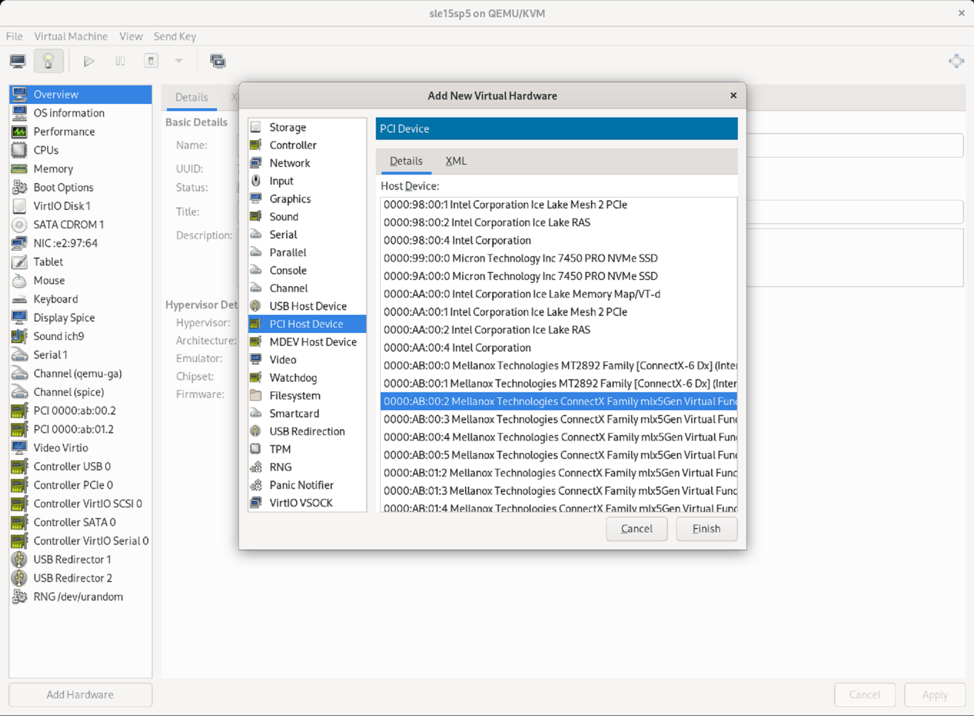
PCI 호스트 장치 목록에서 첫 번째 물리적 포트에서 원하는 가상 NIC를 선택하고 마침을 누릅니다.
이 예에서 0000.AB:00:2 - 0000.AB:00:4는 첫 번째 물리적 포트에 속하고 0000.AB:01:2 - 0000.AB:01:4는 두 번째 물리적 포트에 속합니다.
-
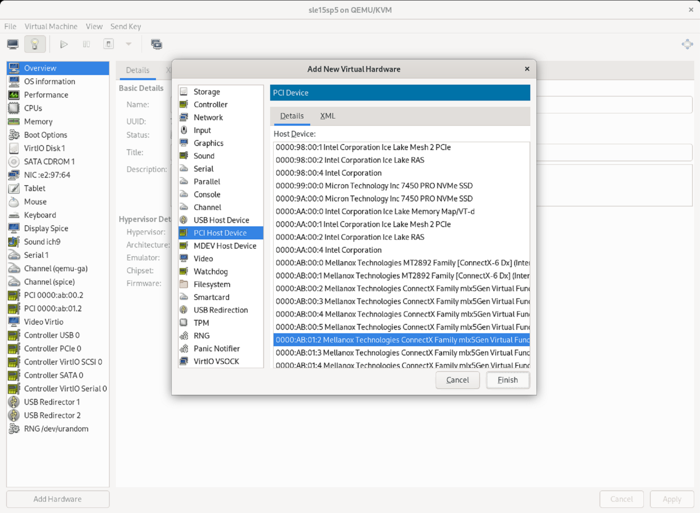
PCI 호스트 장치 목록에서 다음 가상 NIC 포트를 선택하고, 두 번째 물리적 포트에서 가상 포트를 사용하고 *마침*을 선택합니다.
-
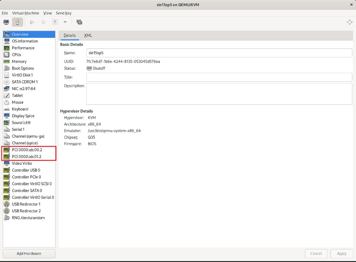
그런 다음 가상 인터페이스가 VM에 할당되고 VM을 시작할 수 있습니다. +
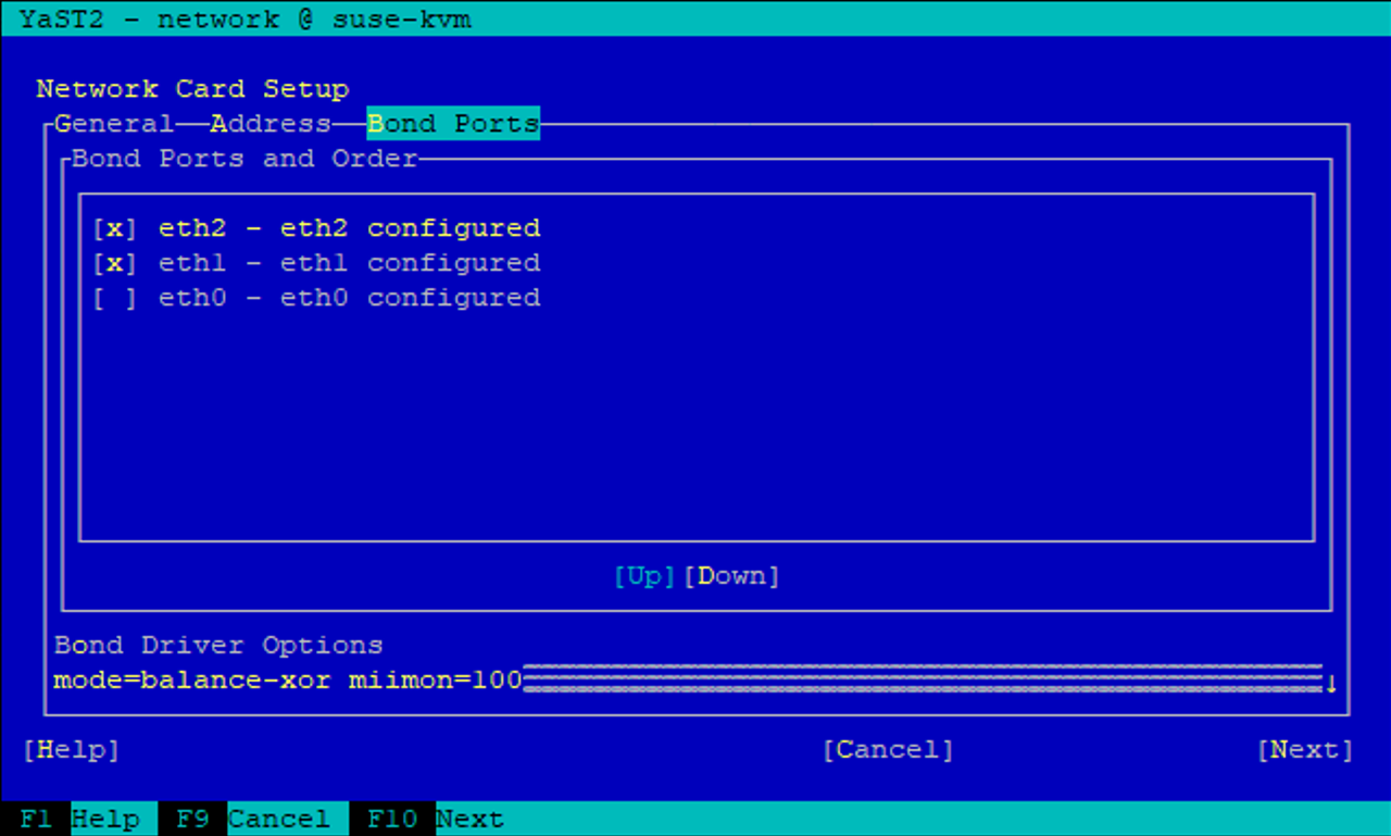
5단계: VM 내에서 네트워크 인터페이스 구성
VM에 로그인하고 두 VF를 본드로 구성합니다. 모드 0 또는 모드 2를 선택하세요. LACP는 물리적 포트에서만 사용할 수 있으므로 LACP를 사용하지 마세요. 아래 그림은 YAST를 사용한 모드 2 구성을 보여줍니다.
다음은 무엇인가요?
SR-IOV 네트워크 인터페이스를 구성한 후"파이버 채널 네트워킹 구성" FCP를 저장 프로토콜로 사용할 경우.