


Configure NVMe over FC switches for VMware in E-Series

 Suggest changes

 PDFs
PDFs
For the NVMe over Fibre Channel protocol, you configure the switches and determine the host port identifiers.

|
Volumes must be set to utilize 512 byte emulation (512e) when using 4096 byte drives to ensure compatibility with VMware. Refer to the SANtricity System Manager online help for more information on setting a volume to use 512-byte emulation (512e). |
|
|
While planning your NVMe over FC configuration, remember that the VMware Configuration Maximums Guide states that the maximum supported NVMe FC initiator ports per server is 2. You must consider this requirement to avoid configuring too many paths. |
Step 1: Record your configuration
You can generate and print a PDF of this page, and then use the following worksheet to record NVMe over Fibre Channel storage configuration information. You need this information as you perform provisioning tasks.
The illustration shows a host connected to an E-Series storage array in two zones. One zone is indicated by the red lines; the other zone is indicated by the blue lines. Each zone contains one initiator port and half of all target ports. Number of controller ports will vary based on the controller model and number of host interface cards (HIC). You may have more (up to 12 per controller) ports available. Print additional PDFs as needed.
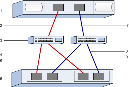
Host identifiers
| Callout No. | Host (initiator) port connections | WWPN |
|---|---|---|
1 |
Host |
not applicable |
2 |
Host port 0 to FC switch zone 0 |
|
7 |
Host port 1 to FC switch zone 1 |
Target identifiers
| Callout No. | Array controller (target) port connections | WWPN |
|---|---|---|
3 |
Switch |
not applicable |
6 |
Array controller (target) |
not applicable |
5 |
Controller A, port 1 to FC switch 1 |
|
5 |
Controller A, port 2 to FC switch 1 |
|
9 |
Controller A, port 3 to FC switch 2 |
|
9 |
Controller A, port 4 to FC switch 2 |
|
4 |
Controller B, port 1 to FC switch 1 |
|
4 |
Controller B, port 2 to FC switch 1 |
|
8 |
Controller B, port 3 to FC switch 2 |
|
8 |
Controller B, port 4 to FC switch 2 |
Host Mapping Information
| Mapping host name | |
|---|---|
Host OS type |
|
Host NQN |
|
Target NQN |
Step 2: Determine the host ports WWPNs
To configure FC zoning, you must determine the worldwide port name (WWPN) of each initiator port.
-
Connect to the ESXi host using SSH or the ESXi shell. To enable the ESXi shell, see Using ESXi Shell in ESXi.
-
Run the following command:
esxcli storage core adapter list
-
Record the initiator WWPN identifiers (UID in the format - fc.WWNN:WWPN). The output will be similar to this example:
HBA Name  Driver    Link State  UID                                   Capabilities         Description
--------  --------  ----------  ------------------------------------  -------------------  -----------
vmhba4    lpfc      link-up     fc.200070b7e4395530:100070b7e4395530  Second Level Lun ID  (0000:5e:00.0) Emulex Corporation Emulex LPe35000/LPe36000 Fibre Channel Adapter
vmhba5    lpfc      link-up     fc.200070b7e4395531:100070b7e4395531  Second Level Lun ID  (0000:5e:00.1) Emulex Corporation Emulex LPe35000/LPe36000 Fibre Channel Adapter
vmhba64   lpfc      link-up     fc.200070b7e4395530:100070b7e4395530                       (0000:5e:00.0) Emulex Corporation Emulex LPe35000/LPe36000 Fibre Channel Adapter
vmhba65   lpfc      link-up     fc.200070b7e4395531:100070b7e4395531                       (0000:5e:00.1) Emulex Corporation Emulex LPe35000/LPe36000 Fibre Channel Adapter
In the example above, the UID for vmhba4 and vmhba64 as well as vmhba5 and vmhba65 are identical. This is expected for FC adapters that support both FCP and NVMe over FC. Record each unique WWPN.
|
|
Another command option is esxcli storage san fc list. This will display more details and the WWPN in hexadecimal format separated by colons.
|
-
Run the following command and record the host NQN (this will be needed later when configuring host mappings):
esxcli nvme info get
Step 3: Configure the NVMe/FC switches
Configuring (zoning) the NVMe over Fibre Channel (FC) switches enables the hosts to connect to the storage array and limits the number of paths. You zone the switches using the management interface for the switches.
Make sure you have the following:
-
Administrator credentials for the switches.
-
The WWPN of each host initiator port and of each controller target port connected to the switch. (Use your HBA utility for discovery.)
|
|
A vendor's HBA utility can be used to upgrade and obtain specific information about the HBA. Refer to the support section of the vendor's website for instructions on how to obtain the HBA utility. |
Each initiator port must be in a separate zone with all of its corresponding target ports. For details about zoning your switches, see the switch vendor's documentation.
-
Log in to the FC switch administration program, and then select the zoning configuration option.
-
Create a new zone that includes the first host initiator port and that also includes all of the target ports that connect to the same FC switch as the initiator.
-
Create additional zones for each FC host initiator port in the switch.
-
Save the zones, and then activate the new zoning configuration.
Please consult the switch vendor's documentation for detailed instructions on configuring zones.