

Replication topologies
 Suggest changes
In ONTAP 9, the physical components of a cluster are visible to cluster administrators, but they are not directly visible to the applications and hosts that use the cluster. The physical components provide a pool of shared resources from which the logical cluster resources are constructed. Applications and hosts access data only through SVMs that contain volumes and LIFs.
Each NetApp SVM is treated as a unique array in Site Recovery Manager. VLSR supports certain array-to-array (or SVM-to-SVM) replication layouts.
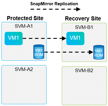
A single VM cannot own data—Virtual Machine Disk (VMDK) or RDM—on more than one VLSR array for the following reasons:
-
VLSR sees only the SVM, not an individual physical controller.
-
An SVM can control LUNs and volumes that span multiple nodes in a cluster.
| Best Practice |
|---|
To determine supportability, keep this rule in mind: to protect a VM by using VLSR and the NetApp SRA, all parts of the VM must exist on only one SVM. This rule applies at both the protected site and the recovery site. |
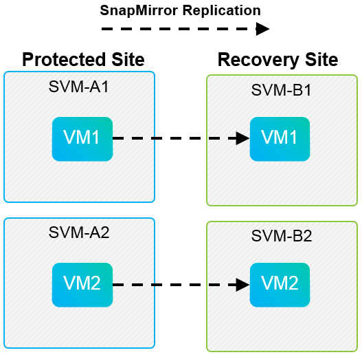
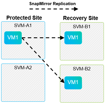
Supported SnapMirror layouts
The following figures show the SnapMirror relationship layout scenarios that VLSR and SRA support. Each VM in the replicated volumes owns data on only one VLSR array (SVM) at each site.
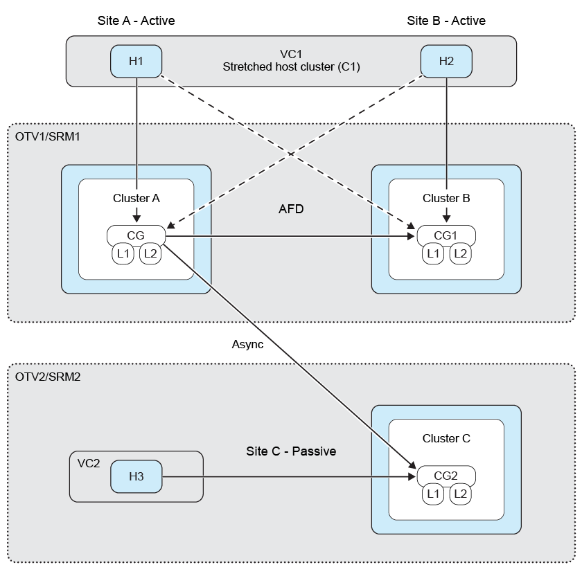
VMFS support with SnapMirror active sync
ONTAP tools 10.3 and later also support protecting your VMFS datastores with SnapMirror active sync(SMas). This enables transparent failover for business continuity between two datacenters (referred to as failure domains) that are relatively close together. Long-distance disaster recovery can then be orchestrated using SnapMirror asynchronous through the ONTAP tools SRA with VLSR.
Datastores are collected together in a consistency group(CG), and the VMs across all datastores will all remain write-order consistent as members of the same CG.
Some examples might be to have sites in Berlin and Hamburg protected by SMas, and a third site replica using SnapMirror asynchronous and protected by VLSR. Another example might be to protect sites in New York and New Jersey using SMas, with a third site in Chicago.
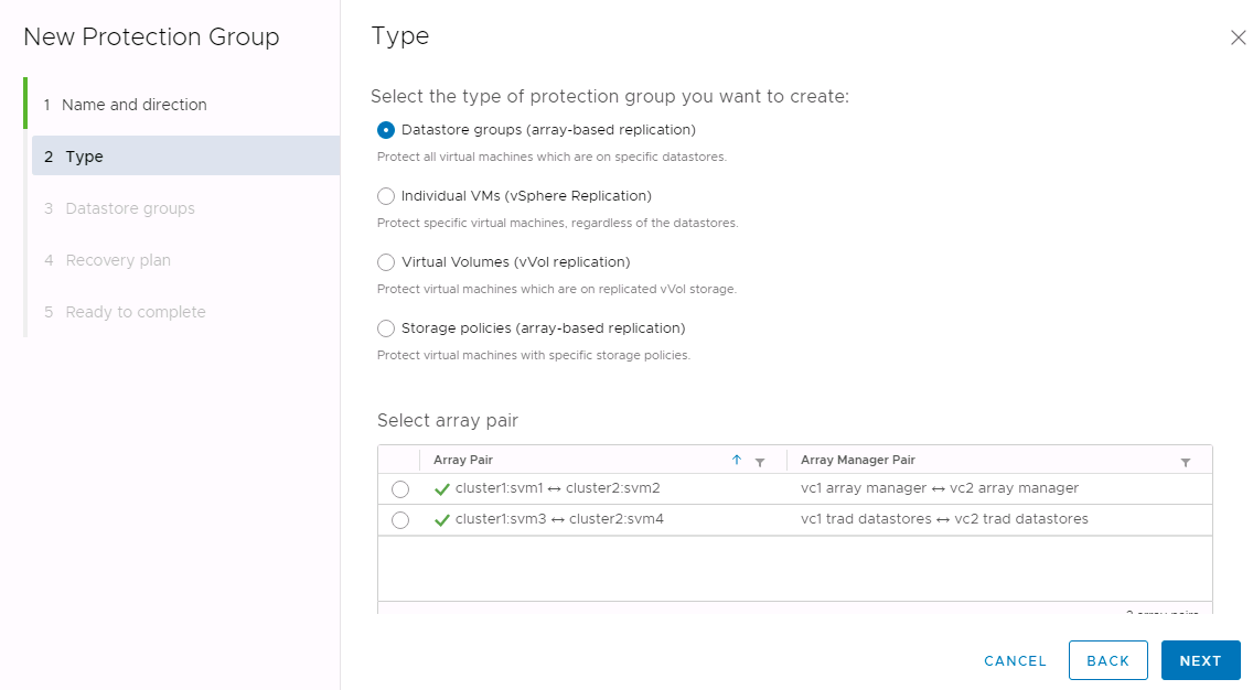
Supported Array Manager layouts
When you use array-based replication (ABR) in VLSR, protection groups are isolated to a single array pair, as shown in the following screenshot. In this scenario, SVM1 and SVM2 are peered with SVM3 and SVM4 at the recovery site. However, you can select only one of the two array pairs when you create a protection group.
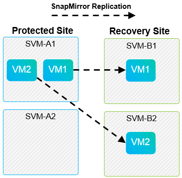
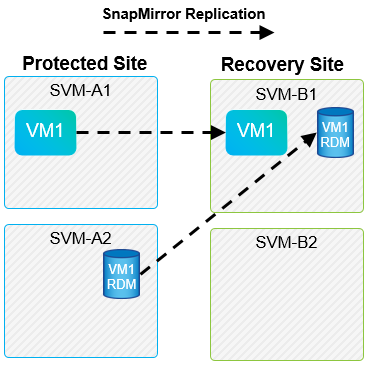
Unsupported layouts
Unsupported configurations have data (VMDK or RDM) on multiple SVMs that is owned by an individual VM. In the examples shown in the following figures, VM1 cannot be configured for protection with VLSR because VM1 has data on two SVMs.
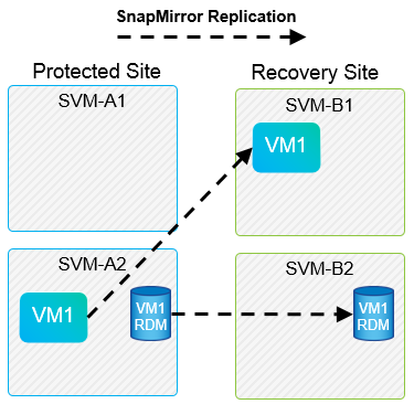
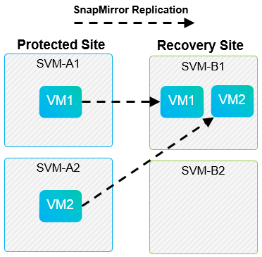
Any replication relationship in which an individual NetApp volume is replicated from one source SVM to multiple destinations in the same SVM or in different SVMs is referred to as SnapMirror fan-out. Fan-out is not supported with VLSR. In the example shown in the following figure, VM1 cannot be configured for protection in VLSR because it is replicated with SnapMirror to two different locations.
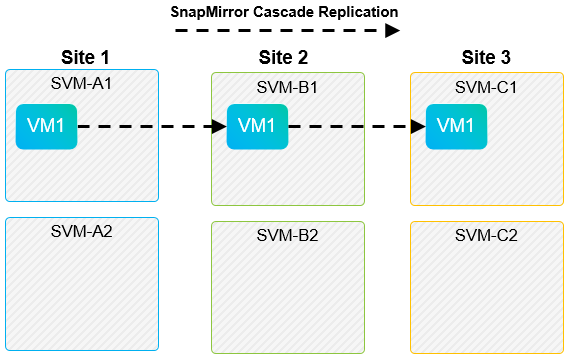
SnapMirror cascade
VLSR does not support cascading of SnapMirror relationships, in which a source volume is replicated to a destination volume and that destination volume is also replicated with SnapMirror to another destination volume. In the scenario shown in the following figure, VLSR cannot be used for failover between any sites.
SnapMirror and SnapVault
NetApp SnapVault software enables disk-based backup of enterprise data between NetApp storage systems. SnapVault and SnapMirror can coexist in the same environment; however, VLSR supports the failover of only the SnapMirror relationships.

|
The NetApp SRA supports the mirror-vault policy type.
|
SnapVault was rebuilt from the ground up for ONTAP 8.2. Although former Data ONTAP 7-Mode users should find similarities, major enhancements have been made in this version of SnapVault. One major advance is the ability to preserve storage efficiencies on primary data during SnapVault transfers.
An important architectural change is that SnapVault in ONTAP 9 replicates at the volume level as opposed to at the qtree level, as is the case in 7-Mode SnapVault. This setup means that the source of a SnapVault relationship must be a volume, and that volume must replicate to its own volume on the SnapVault secondary system.
In an environment in which SnapVault is used, specifically named snapshots are created on the primary storage system. Depending on the configuration implemented, the named snapshots can be created on the primary system by a SnapVault schedule or by an application such as NetApp Active IQ Unified Manager. The named snapshots that are created on the primary system are then replicated to the SnapMirror destination, and from there they are vaulted to the SnapVault destination.
A source volume can be created in a cascade configuration in which a volume is replicated to a SnapMirror destination in the DR site, and from there it is vaulted to a SnapVault destination. A source volume can also be created in a fan-out relationship in which one destination is a SnapMirror destination and the other destination is a SnapVault destination. However, SRA does not automatically reconfigure the SnapVault relationship to use the SnapMirror destination volume as the source for the vault when VLSR failover or replication reversal occurs.
For the latest information about SnapMirror and SnapVault for ONTAP 9, see TR-4015 SnapMirror Configuration Best Practice Guide for ONTAP 9.
| Best Practice |
|---|
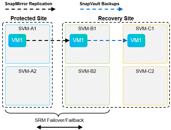
If SnapVault and VLSR are used in the same environment, NetApp recommends using a SnapMirror to SnapVault cascade configuration in which SnapVault backups are normally performed from the SnapMirror destination at the DR site. In the event of a disaster, this configuration makes the primary site inaccessible. Keeping the SnapVault destination at the recovery site allows SnapVault backups to be reconfigured after failover so that SnapVault backups can continue while operating at the recovery site. |
In a VMware environment, each datastore has a universal unique identifier (UUID), and each VM has a unique managed object ID (MOID). These IDs are not maintained by VLSR during failover or failback. Because datastore UUIDs and VM MOIDs are not maintained during failover by VLSR, any applications that depend on these IDs must be reconfigured after VLSR failover. An example application is NetApp Active IQ Unified Manager, which coordinates SnapVault replication with the vSphere environment.
The following figure depicts a SnapMirror to SnapVault cascade configuration. If the SnapVault destination is at the DR site or at a tertiary site that is not affected by an outage at the primary site, the environment can be reconfigured to allow backups to continue after failover.
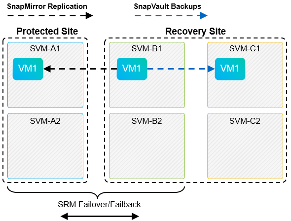
The following figure depicts the configuration after VLSR has been used to reverse SnapMirror replication back to the primary site. The environment has also been reconfigured such that SnapVault backups are occurring from what is now the SnapMirror source. This setup is a SnapMirror SnapVault fan-out configuration.
After vsrm performs failback and a second reversal of the SnapMirror relationships, the production data is back at the primary site. This data is now protected in the same way that it was before the failover to the DR site—through SnapMirror and SnapVault backups.
Use of Qtrees in Site Recovery Manager environments
Qtrees are special directories that allow the application of file system quotas for NAS. ONTAP 9 allows the creation of qtrees, and qtrees can exist in volumes that are replicated with SnapMirror. However, SnapMirror does not allow replication of individual qtrees or qtree-level replication. All SnapMirror replication is at the volume level only. For this reason, NetApp does not recommend the use of qtrees with VLSR.
Mixed FC and iSCSI environments
With the supported SAN protocols (FC, FCoE, and iSCSI), ONTAP 9 provides LUN services—that is, the ability to create and map LUNs to attached hosts. Because the cluster consists of multiple controllers, there are multiple logical paths that are managed by multipath I/O to any individual LUN. Asymmetric logical unit access (ALUA) is used on the hosts so that the optimized path to a LUN is selected and is made active for data transfer. If the optimized path to any LUN changes (for example, because the containing volume is moved), ONTAP 9 automatically recognizes and nondisruptively adjusts for this change. If the optimized path becomes unavailable, ONTAP can nondisruptively switch to any other available path.
VMware VLSR and NetApp SRA support the use of the FC protocol at one site and the iSCSI protocol at the other site. It does not support having a mix of FC-attached datastores and iSCSI-attached datastores in the same ESXi host or in different hosts in the same cluster, however. This configuration is not supported with VLSR because, during the VLSR failover or test failover, VLSR includes all FC and iSCSI initiators in the ESXi hosts in the request.
| Best Practice |
|---|
VLSR and SRA support mixed FC and iSCSI protocols between the protected and recovery sites. However, each site should be configured with only one protocol, either FC or iSCSI, not both protocols at the same site. If a requirement exists to have both FC and iSCSI protocols configured at the same site, NetApp recommends that some hosts use iSCSI and other hosts use FC. NetApp also recommends in this case that VLSR resource mappings be set up so that the VMs are configured to fail over into one group of hosts or the other. |