

Replace node1 AFF A800 or AFF C800 controller module
 Suggest changes
Replace the node1 AFF A800 or AFF C800 controller module with an AFF A90, AFF A70, or AFF C80 controller module.
At this stage, node1 is down and all data is served by node2. You must take care to remove only the node1 controller module. When looking at the controllers from the rear of the system, the controllers are stacked, with controller A typically on top. The controller label is located on the chassis directly above the controller module.

|
Don't power off the chassis because node1 and node2 are in the same chassis and connected to the same power supplies. |
If you are not already grounded, correctly ground yourself.
Step 1: Remove the AFF A800 or AFF C800 controller module
Remove the cable management device from the existing node1 module and move the controller slightly out of the chassis.
-
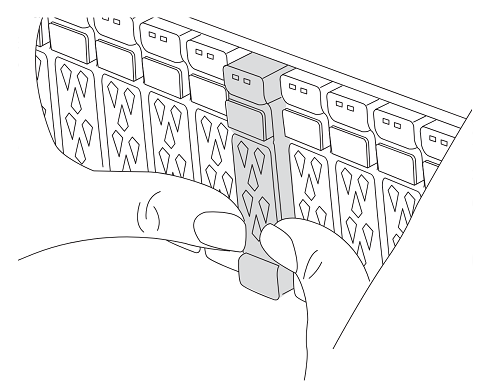
Ensure that all drives in the chassis are firmly seated against the midplane by using your thumbs to push each drive until you feel a positive stop.
Video - Confirm drive seating
-
Check the controller drives based on the system status:
-
On the healthy controller, check if any active RAID group is in a degraded state, failed state, or both:
storage aggregate show -raidstatus !*normal*-
If the command returns
There are no entries matching your query., continue to go to the next sub-step to check for missing drives. -
If the command returns any other results, collect the AutoSupport data from both controllers and contact NetApp Support for further assistance.
system node autosupport invoke -node * -type all -message '<message_name>'
-
-
Check for missing drive issues for both the file system or spare drives:
event log show -severity * -node * -message-name *disk.missing*-
If the command returns
There are no entries matching your query., continue to go to the next step. -
If the command returns any other results, collect the AutoSupport data from both controllers and contact NetApp Support for further assistance.
system node autosupport invoke -node * -type all -message '<message_name>'
-
-
-
Remove the power cable retainers, then unplug the cables from the power supplies.
-
Unplug the node1 controller module power supplies from the source.
-
Release the power cable retainers, and then unplug the cables from the power supplies.
-
Loosen the hook and loop strap binding the cables to the cable management device, and then unplug the system cables and SFP and QSFP modules (if needed) from the controller module, keeping track of where the cables were connected.
Leave the cables in the cable management device so that when you reinstall the cable management device, the cables are organized.
-
Remove the cable management device from the controller module and set it aside.
-
Press down on both of the locking latches, and then rotate both latches downward at the same time.
The controller module moves slightly out of the chassis.
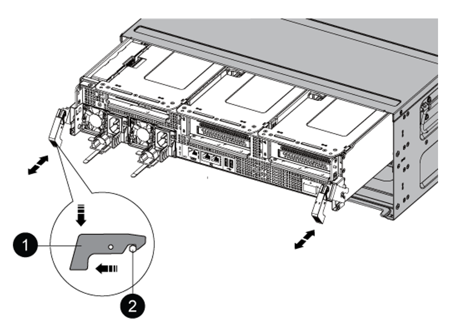

Locking latch

Locking pin
Step 2: Install the AFF A90, AFF A70, or AFF C80 controller module
Install, cable, and connect the AFF A90, AFF A70, or AFF C80 controller module in node1.
-
Align the end of the controller module with the opening in the chassis, and then gently push the controller module halfway into the system.

Don't completely insert the controller module in the chassis until instructed to do so later in the procedure. 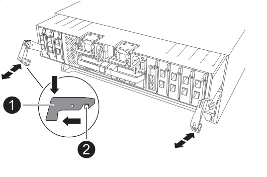
-
Cable the management and console ports to the node1 controller module.
When you insert the node1 controller module in the next step, node1 immediately starts BIOS initialization followed by AUTOBOOT because the chassis is already powered ON. You avoid this AUTOBOOT by connecting the serial and console cables before inserting the module. -
On the front of the chassis, use your thumbs to firmly push each drive in to the top and bottom disk bays until you feel a positive stop. This ensures that the drives are firmly seated against the chassis midplane.
-
Go to the rear of the chassis.
-
-
With the cam handle in the open position, firmly push the controller module in until it meets the midplane and is fully seated. The locking latch rises when the controller module is fully seated. Close the cam handle to the locked position.
To avoid damaging the connectors, don't use excessive force when sliding the controller module into the chassis. -
Connect the serial console as soon as the module is seated and be ready to interrupt AUTOBOOT of node1.
-
After you interrupt AUTOBOOT, node1 stops at the LOADER prompt.
If you do not interrupt AUTOBOOT on time and node1 starts booting, wait for the prompt and enter Ctrl-C to go into the boot menu. After the node stops at the boot menu, use option
8to reboot the node and interrupt AUTOBOOT during reboot. -
At the LOADER> prompt of node1, set the default environment variables:
set-defaults -
Save the default environment variables settings:
saveenv
After installing the AFF A90, AFF A70, or AFF C80 controller module, netboot node1.