

Replace the boot media for automated boot recovery - AFF C250
 Suggest changes
The boot media in your AFF C250 system stores essential firmware and configuration data. The replacement process involves removing and opening the controller module, removing the impaired boot media, installing the replacement boot media in the controller module, and then reinstalling the controller module.
The automated boot media recovery process is supported only in ONTAP 9.18.1 and later. If your storage system is running an earlier version of ONTAP, use the manual boot recovery procedure.
The boot media is located inside the controller module under the air duct, and is accessed by removing the controller module from the system.
Step 1: Remove the controller module
-
If you are not already grounded, properly ground yourself.
-
Unplug the controller module power supplies from the source.
-
Release the power cable retainers, and then unplug the cables from the power supplies.
-
Unplug the I/O cables from the controller module.
-
Insert your forefinger into the latching mechanism on either side of the controller module, press the lever with your thumb, and gently pull the controller a few inches out of the chassis.

If you have difficulty removing the controller module, place your index fingers through the finger holes from the inside (by crossing your arms). 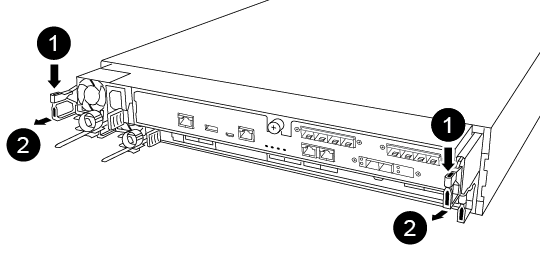

Lever

Latching mechanism
-
Using both hands, grasp the controller module sides and gently pull it out of the chassis and set it on a flat, stable surface.
-
Turn the thumbscrew on the front of the controller module anti-clockwise and open the controller module cover.
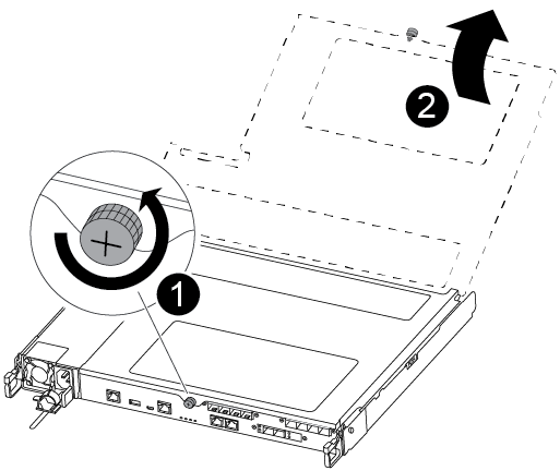
Thumbscrew
Controller module cover.
-
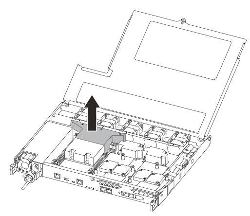
Lift out the air duct cover.
Step 2: Replace the boot media
You can use the following video or the tabulated steps to replace the boot media:
-
Locate and replace the impaired boot media from the controller module and replace it:
You need a #1 magnetic Phillips head screwdriver to remove the screw that holds the boot media in place. Due to the space constraints within the controller module, you should also have a magnet to transfer the screw on to so that you do not lose it. 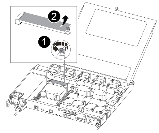
Remove the screw securing the boot media to the motherboard in the controller module.
Lift the boot media out of the controller module.
-
Using the #1 magnetic screwdriver, remove the screw from the impaired boot media, and set it aside safely on the magnet.
-
Gently lift the impaired boot media directly out of the socket and set it aside.
-
Remove the replacement boot media from the antistatic shipping bag and align it into place on the controller module.
-
Using the #1 magnetic screwdriver, insert and tighten the screw on the boot media.
Do not over-tighten the screw or you might damage the boot media.
-
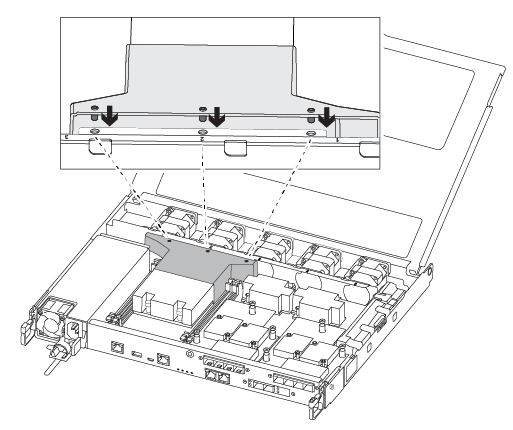
Install the air duct.
-
Close the controller module cover and tighten the thumbscrew.
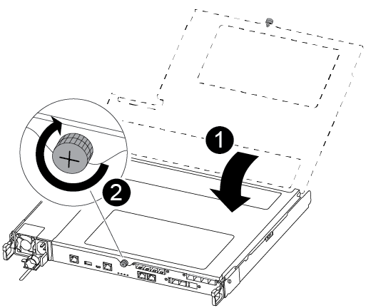
Controller module cover
Thumbscrew
-
-
Install the controller module:
-
Align the end of the controller module with the opening in the chassis, and then gently push the controller module halfway into the system.
-
Push the controller module all the way into the chassis:
-
Place your index fingers through the finger holes from the inside of the latching mechanism.
-
Press your thumbs down on the orange tabs on top of the latching mechanism and gently push the controller module over the stop.
-
Release your thumbs from the top of the latching mechanisms and continue pushing until the latching mechanisms snap into place.
The controller module should be fully inserted and flush with the edges of the chassis.
-
-
Reconnect the controller module I/O cables.
-
Plug the power cords into the power supplies, reinstall the power cable locking collar, and then connect the power supplies to the power source.
The controller module begins to boot and stops at the LOADER prompt.
After physically replacing the impaired boot media, restore the ONTAP image from the partner node.