

Recommended FC and FCoE zoning configurations for ONTAP systems
 Suggest changes
You should create a zoning configuration if your host does not have a multipathing solution installed, if four or more hosts are connected to your SAN or if Selective LUN Mapping is not implemented on the nodes in your cluster.
In the recommended FC and FCoE zoning configuration, each zone includes one initiator port and one or more target LIFs. This configuration allows each host initiator to access any node, while preventing hosts accessing the same node from seeing see each other's ports
Add all LIFs from the storage virtual machine (SVM) to the zone with the host initiator. This allows you to move volumes or LUNs without editing your existing zones or creating new zones.
Dual-fabric zoning configurations
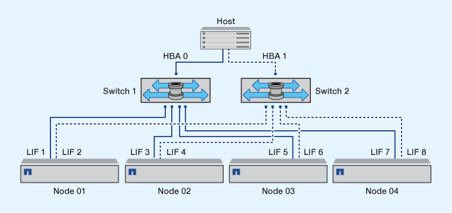
Dual-fabric zoning configurations are recommended because they provide protection against data loss due to a single component failure. In a dual-fabric configuration, each host initiator is connected to each node in the cluster using different switches. If one switch becomes unavailable, data access is maintained through the remaining switch. Multipathing software is required on the host to manage multiple paths.
In the following figure, the host has two initiators and is running multipathing software. There are two zones. Selective LUN Mapping (SLM) is configured so that all nodes are considered as reporting nodes.

|
The naming convention used in this figure is just a recommendation of one possible naming convention that you can choose to use for your ONTAP solution. |
-
Zone 1: HBA 0, LIF_1, LIF_3, LIF_5, and LIF_7
-
Zone 2: HBA 1, LIF_2, LIF_4, LIF_6, and LIF_8
Each host initiator is zoned through a different switch. Zone 1 is accessed through Switch 1. Zone 2 is accessed through Switch 2.
Each host can access a LIF on every node. This enables the host to still access its LUNs if a node fails. SVMs have access to all iSCSI and FC LIFs on every node in the cluster based on your SLM reporting nodes configuration. You can use SLM, portsets, or FC switch zoning to reduce the number of paths from an SVM to the host and the number of paths from an SVM to a LUN.
If the configuration includes more nodes, the LIFs for the additional nodes are included in these zones..
|
|
The host operating system and multipathing software have to support the number of paths that is being used to access the LUNs on the nodes. |
Single-fabric zoning
In a single-fabric configuration, you connect each host initiator to each storage node through a single switch. Single-fabric zoning configurations are not recommended because they do not provide protection against data loss due to a single component failure. If you choose to configure single-fabric zoning, each host should have two initiators for multipathing to provide resiliency in the solution. Multipathing software is required on the host to manage multiple paths.
Each host initiator should have a minimum of one LIF from each node that the initiator can access. The zoning should allow at least one path from the host initiator to the HA pair of nodes in the cluster to provide a path for LUN connectivity. This means that each initiator on the host might only have one target LIF per node in its zone configuration. If there is a requirement for multipathing to the same node or multiple nodes in the cluster, then each node will have multiple LIFs per node in its zone configuration. This enables the host to still access its LUNs if a node fails or a volume containing the LUN is moved to a different node. This also requires the reporting nodes to be set appropriately.
When using Cisco FC and FCoE switches, a single fabric zone must not contain more than one target LIF for the same physical port. If multiple LIFs on the same port are in the same zone, then the LIF ports might fail to recover from a connection loss.
In the following figure, the host has two initiators and is running multipathing software. There are two zones:
|
|
The naming convention used in this figure is just a recommendation of one possible naming convention that you can choose to use for your ONTAP solution. |
-
Zone 1: HBA 0, LIF_1, and LIF_3
-
Zone 2: HBA 1, LIF_2, and LIF_4
If the configuration includes more nodes, the LIFs for the additional nodes are included in these zones.s.
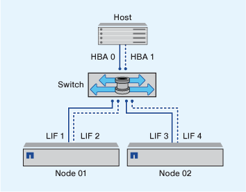
In this example, you could also have all four LIFs in each zone. In that case, the zones would be as follows:
-
Zone 1: HBA 0, LIF_1, LIF_2, LIF_3, and LIF_4
-
Zone 2: HBA 1, LIF_1, LIF_2, LIF_3, and LIF_4
|
|
The host operating system and multipathing software have to support the number of supported paths that are being used to access the LUNs on the nodes. To determine the number of paths used to access the LUNs on nodes, see the SAN configuration limits section. |
Zoning restrictions for Cisco FC and FCoE switches
When using Cisco FC and FCoE switches, certain restrictions apply to the use of physical ports and logical interfaces (LIFs) in zones.
-
FC-NVMe and FC can share the same 32 Gb physical port
-
FC-NVMe and FCoE cannot share the same physical port
-
FC and FCoE can share the same physical port but their protocol LIFs must be in separate zones.
-
A zone can contain a LIF from every target port in the cluster.
Verify the SLM configuration so that you do not to exceed the maximum number of paths allowed to the host.
-
Each LIF on a given port must be in a separate zone from other LIFs on that port
-
LIFs on different physical ports can be in the same zone.