

Deploy hardware
 Suggest changes
Each building block consists of two validated x86 file nodes directly connected to two block nodes using HDR (200Gb) InfiniBand cables.

|
A minimum of two building blocks are required to establish quorum in the failover cluster. A two-node cluster has limitations that might prevent a successful failover from occurring. You can configure a two-node cluster by incorporating a third device as a tiebreaker; however, this documentation does not describe that design. |
The following steps are identical for each building block in the cluster, regardless of whether it is used to run both BeeGFS metadata and storage services, or just storage services, unless it is otherwise noted.
-
Set up each BeeGFS file node with four Host Channel Adapters (HCAs) using the models specified in the Technical requirements. Insert the HCAs into the PCIe slots of your file node according to the specifications below:
-
Lenovo ThinkSystem SR665 V3 Server: Use PCIe slots 1, 2, 4, and 5.
-
Lenovo ThinkSystem SR665 Server: Use PCIe slots 2, 3, 5, and 6.
-
-
Configure each BeeGFS block node with a dual-port 200Gb Host Interface Card (HIC) and install the HIC in each of its two storage controllers.
Rack the building blocks so the two BeeGFS file nodes are above the BeeGFS block nodes. The following figure shows the correct hardware configuration for the BeeGFS building block using Lenovo ThinkSystem SR665 V3 servers as the file nodes (rear view).
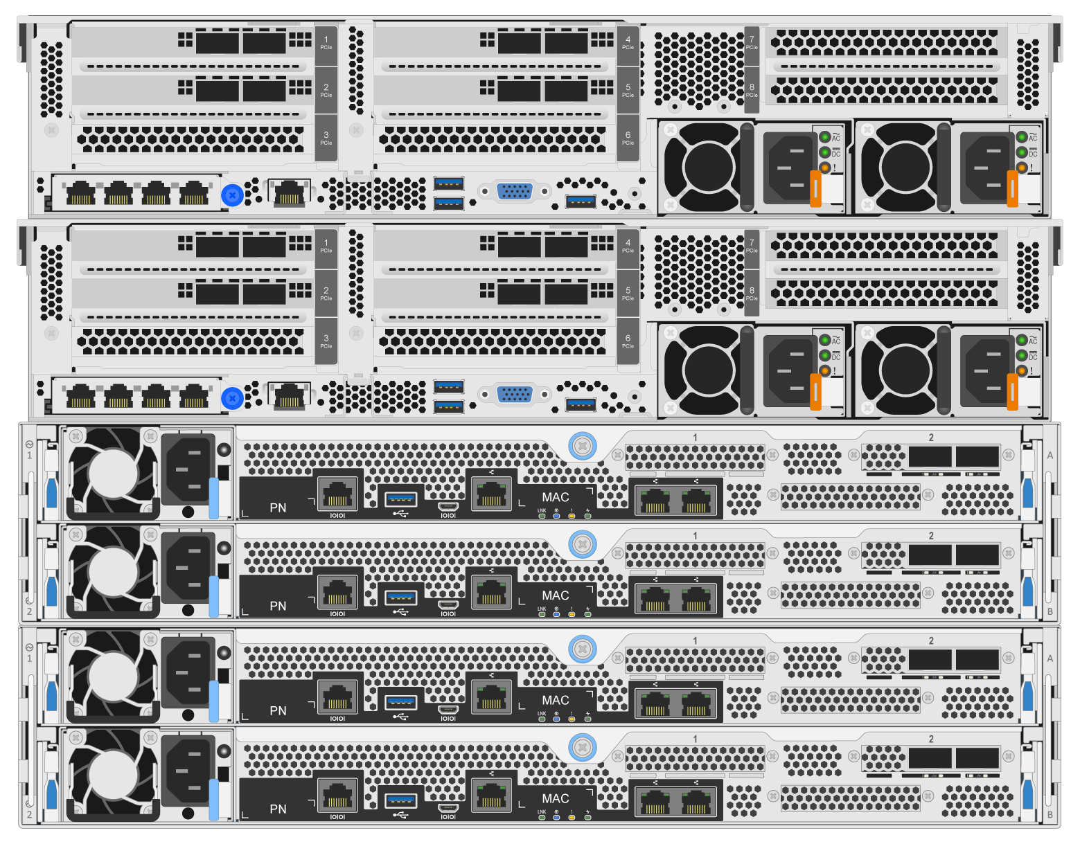
The power supply configuration for production use cases should typically use redundant PSUs. -
If needed, install the drives in each of the BeeGFS block nodes.
-
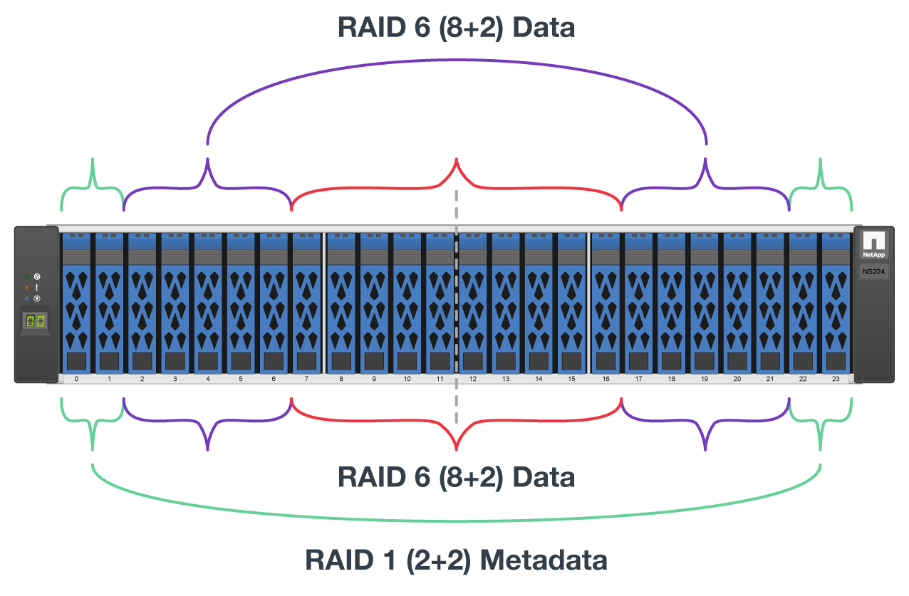
If the building block will be used to run BeeGFS metadata and storage services and smaller drives are used for metadata volumes, verify that they are populated in the outermost drive slots, as shown in the figure below.
-
For all building block configurations, if a drive enclosure is not fully populated, make sure that an equal number of drives are populated in slots 0–11 and 12–23 for optimal performance.
-
-
Connect the block and file nodes using the 1m InfiniBand HDR 200Gb direct attach copper cables, so that they match the topology shown in the following figure.
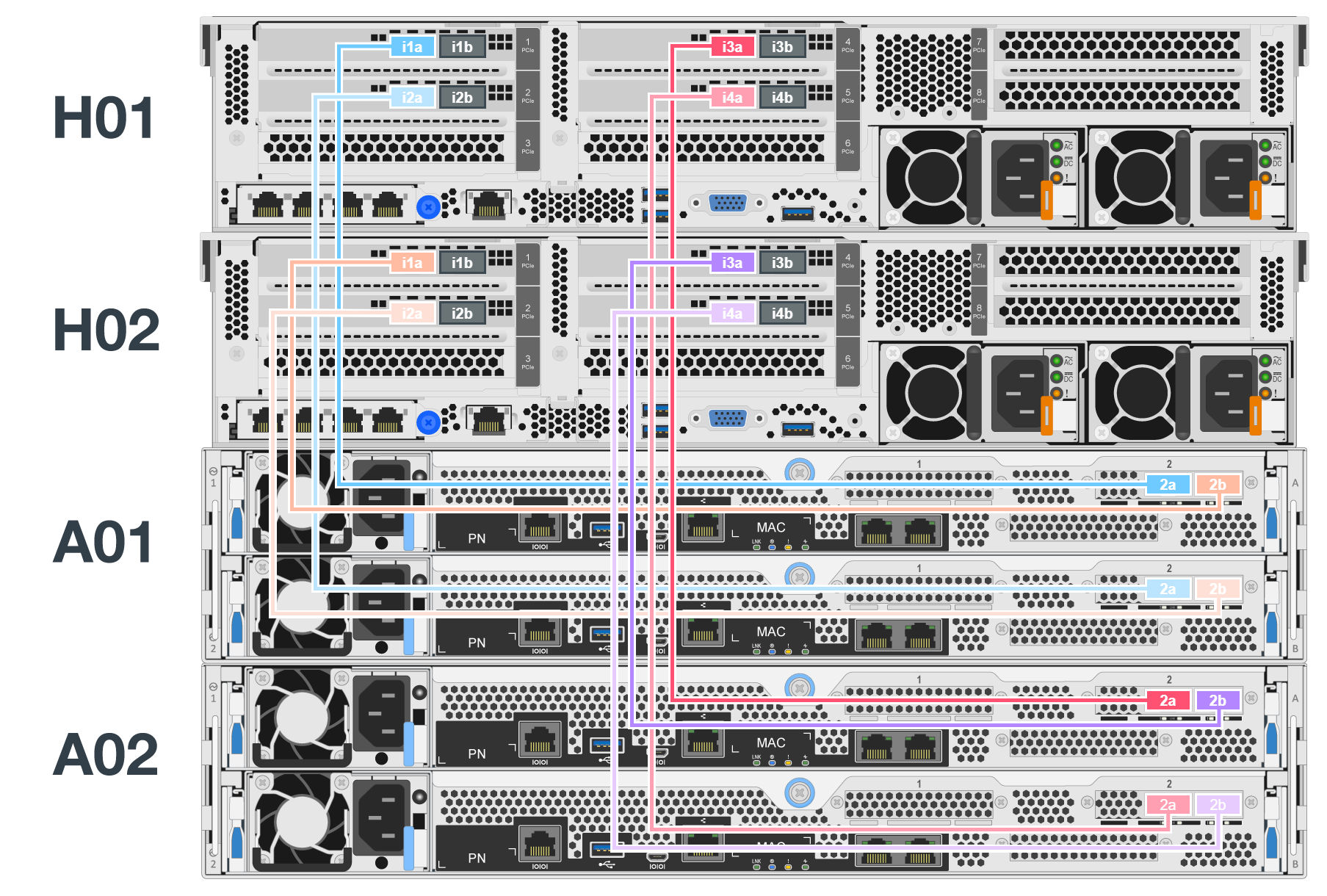
The nodes across multiple building blocks are never directly connected. Each building block should be treated as a standalone unit and all communication between building blocks occurs through network switches. -
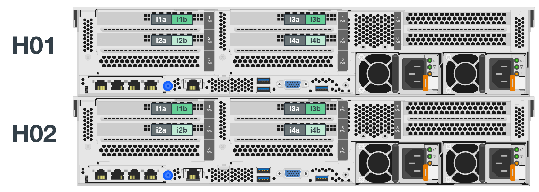
Connect the remaining InfiniBand ports on the file node to the storage network's InfiniBand switch using the 2m InfiniBand cables specific to your InfiniBand storage switch.
When using splitter cables to connect the storage switch to file nodes, one cable should branch out from the switch and connect to the ports outlined in light green. Another splitter cable should branch out from the switch and connect to the ports outlined in dark green.
Additionally, for storage networks with redundant switches, ports outlined in light green should connect to one switch, while ports in dark green should connect to another switch.
-
As needed, assemble additional building blocks following the same cabling guidelines.
The total number of building blocks that can be deployed in a single rack depends on the available power and cooling at each site.