Record your FC configuration in E-Series - Linux
 Suggest changes


You can generate and print a PDF of this page, and then use the following worksheet to record FC storage configuration information. You need this information to perform provisioning tasks.
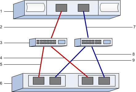
The illustration shows a host connected to an E-Series storage array in two zones. One zone is indicated by the blue line; the other zone is indicated by the red line. Any single port has two paths to the storage (one to each controller).

Host identifiers
| Callout No. | Host (initiator) port connections | WWPN |
|---|---|---|
1 |
Host |
not applicable |
2 |
Host port 0 to FC switch zone 0 |
|
7 |
Host port 1 to FC switch zone 1 |
Target identifiers
| Callout No. | Array controller (target) port connections | WWPN |
|---|---|---|
3 |
Switch |
not applicable |
6 |
Array controller (target) |
not applicable |
5 |
Controller A, port 1 to FC switch 1 |
|
9 |
Controller A, port 2 to FC switch 2 |
|
4 |
Controller B, port 1 to FC switch 1 |
|
8 |
Controller B, port 2 to FC switch 2 |
Mapping host
Mapping host name |
|
Host OS type |


