Change the host protocol - E2800
 Suggest changes


If you have an E2800 storage array with SFP+ (optical) host ports, you can change the host port protocol from Fibre Channel (FC) to iSCSI or from iSCSI to FC.
You can change the protocol used by the host ports built into the controller (baseboard host ports), the protocol used by the host ports on the host interface card (HIC ports), or the protocol of all host ports.
Step 1: Determine whether you have dual-protocol SFPs
Use SANtricity System Manager to determine what type of SFP transceivers you have. Because these SFPs can be used with both FC and iSCSI protocols, they are referred to as dual-protocol or unified SFPs.
-
From SANtricity System Manager, select Support.
-
Select the Support Center tile.
-
On the Support Resources tab, locate and select the Storage Array Profile link.
-
Type SFP in the text box, and click Find.
-
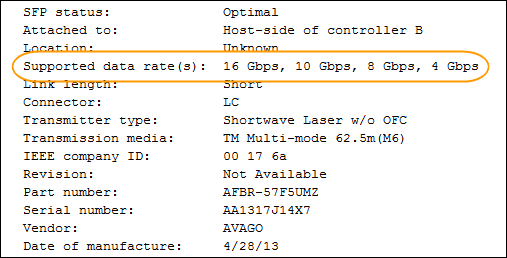
For each SFP listed in the Storage Array Profile, locate the entry for Supported data rate(s).
-
Refer to the table to determine whether you can reuse the SFPs, as follows:
Supported data rate(s) SFP type Supported protocol 16 Gbps, 10 Gbps, 4 Gbps
Dual-protocol
-
FC: 16 Gbps, 4 Gbps
-
iSCSI:10 Gbps
25 Gbps, 10 Gbps
25 Gbps. 10 Gbps,
iSCSI only
32 Gbps, 16 Gbps, 8 Gbps, 4 Gbps
32 Gbps, 16 Gbps
FC only
-
If you have dual-protocol SFPs, you can continue using them after you convert the protocol.
The dual-protocol SFPs do not support 1 Gb iSCSI. If you are converting host ports to iSCSI, be aware that the dual-protocol SFPs support only a 10 Gb link to the connected port. -
If you have 16 Gbps SFPs, and you are converting host ports to iSCSI, you must remove the SFPs and replace them with dual-protocol or 10 Gbps SFPs after converting the protocol. As needed, you can also use 10 Gbps iSCSI copper by using a special Twin-Ax cable with SFPs.
8Gbps FC SFPs are NOT supported in the E28xx or E57xx controllers. ONLY 16Gbps and 32 Gbps FC SFPs are supported. -
If you have 10 Gbps SFPs, and you are converting host ports to FC, you must remove the SFPs from these ports and replace them with dual-protocol or 16 Gbps SFPs after converting the protocol.
-
Step 2: Obtain the feature pack
To obtain the feature pack, you need the serial number from the controller shelf, a Feature Activation Code, and the Feature Enable Identifier for the storage array.
-
Locate the serial number.
-
From SANtricity System Manager, select .
-
With the Support Resources tab selected, scroll to the View top storage array properties section.
-
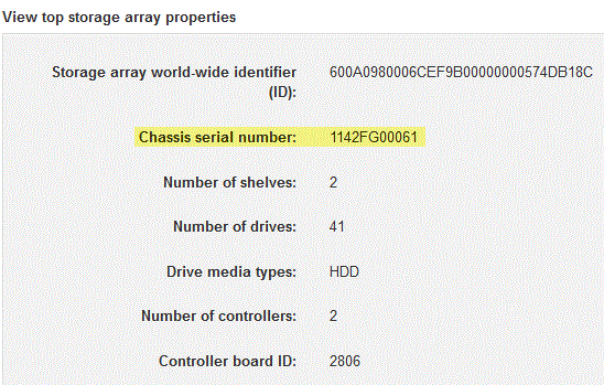
Locate the Chassis Serial Number, and copy this value to a text file.
-
-
Locate the feature pack submodel ID.
-
On the Support Resources tab, locate and select the Storage Array Profile link.
-
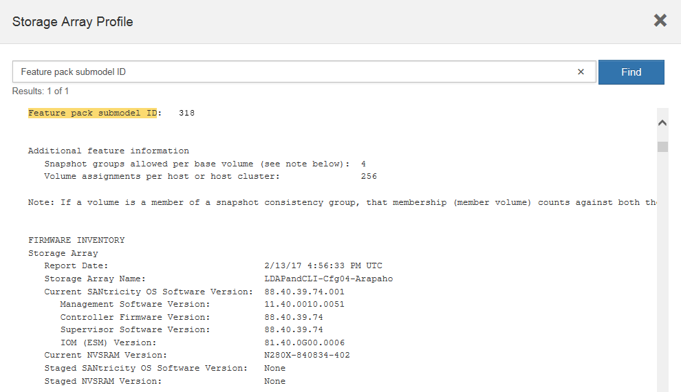
Type feature pack submodel ID in the text box, and click Find.
"Submodel" may also be written as "sub-model." -
Locate the feature pack submodel ID for the starting configuration.
-
-
Using the feature pack submodel ID, locate the corresponding Controller submodel ID for the starting configuration and find the Feature Activation Code for the desired ending configuration within the table below. Then, copy that Feature Activation Code to a text file.
Starting configuration Ending configuration Feature Activation Code Controller submodel ID
Baseboard ports
HIC ports
Controller submodel ID
Baseboard ports
HIC ports
318
FC
FC
319
FC
iSCSI
ZGW-4L2-Z36IJ
320
iSCSI
FC
4GZ-NL2-Z4NRP
321
iSCSI
iSCSI
TG2-7L2-Z5485
no HIC or not an optical HIC
321
iSCSI
TG2-7L2-Z5485
319
FC
iSCSI
318
FC
FC
1G5-QL2-Z7LFC
320
iSCSI
FC
FG7-AL2-Z82RW
321
iSCSI
iSCSI
5G7-0K2-Z0G8X
320
iSCSI
FC
318
FC
FC
4GP-HL2-ZYRKP
319
FC
iSCSI
PGU-KL2-Z1P7I
321
iSCSI
iSCSI
BGA-8K2-ZQWM5
321
iSCSI
iSCSI
318
FC
FC
SGH-UK2-ZUCJG
319
FC
iSCSI
1GK-EK2-ZVSW1
320
iSCSI
FC
AGM-XL2-ZWA8A
Starting configuration Ending configuration Feature Activation Code Controller submodel ID
Baseboard ports
HIC ports
Controller submodel ID
Baseboard ports
HIC ports
338
FC
FC
339
FC
iSCSI
PGC-RK2-ZREUT
340
iSCSI
FC
MGF-BK2-ZSU3Z
341
iSCSI
iSCSI
NGR-1L2-ZZ8QC
no HIC or not an optical HIC
341
iSCSI
NGR-1L2-ZZ8QC
339
FC
iSCSI
338
FC
FC
DGT-7M2-ZKBMD
340
iSCSI
FC
GGA-TL2-Z9J50
341
iSCSI
iSCSI
WGC-DL2-ZBZIB
340
iSCSI
FC
338
FC
FC
4GM-KM2-ZGWS1
339
FC
iSCSI
PG0-4M2-ZHDZ6
341
iSCSI
iSCSI
XGR-NM2-ZJUGR
341
iSCSI
iSCSI
338
FC
FC
3GE-WL2-ZCHNY
339
FC
iSCSI
FGH-HL2-ZDY3R
340
iSCSI
FC
VGJ-1L2-ZFFEW
If your Controller submodel ID is not listed, contact NetApp Support. -
In System Manager, locate the Feature Enable Identifier.
-
Go to .
-
Scroll down to Add-ons.
-
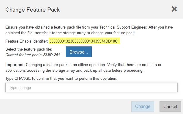
Under Change Feature Pack, locate the Feature Enable Identifier.
-
Copy and paste this 32-digit number to a text file.
-
-
Go to NetApp License Activation: Storage Array Premium Feature Activation, and enter the information required to obtain the feature pack.
-
Chassis serial number
-
Feature Activation Code
-
Feature Enable Identifier
The Premium Feature Activation web site includes a link to “Premium Feature Activation Instructions.” Do not attempt to use those instructions for this procedure.
-
-
Choose whether to receive the key file for the feature pack in an email or download it directly from the site.
Step 3: Stop host I/O
You must stop all I/O operations from the host before converting the protocol of the host ports. You cannot access data on the storage array until you successfully complete the conversion.
-
Ensure that no I/O operations are occurring between the storage array and all connected hosts. For example, you can perform these steps:
-
Stop all processes that involve the LUNs mapped from the storage to the hosts.
-
Ensure that no applications are writing data to any LUNs mapped from the storage to the hosts.
-
Unmount all file systems associated with volumes on the array.
The exact steps to stop host I/O operations depend on the host operating system and the configuration, which are beyond the scope of these instructions. If you are not sure how to stop host I/O operations in your environment, consider shutting down the host. Possible data loss — If you continue this procedure while I/O operations are occurring, the host application might lose access to the data because the storage is not accessible.
-
-
If the storage array participates in a mirroring relationship, stop all host I/O operations on the secondary storage array.
-
Wait for any data in cache memory to be written to the drives.
The green Cache Active LED on the back of each controller is on when cached data needs to be written to the drives. You must wait for this LED to turn off.

Callout Type of host ports (1)
Cache Active LED
-
From the Home page of SANtricity System Manager, select View Operations in Progress.
-
Wait for all operations to complete before continuing with the next step.
Step 4: Change the feature pack
Change the feature pack to convert the host protocol of the baseboard host ports, the IB HIC ports, or both types of ports.
-
From SANtricity System Manager, select .
-
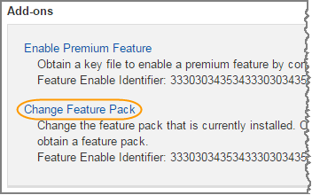
Under Add-ons, select Change Feature Pack.
-
Click Browse, and then select the feature pack you want to apply.
-
Type
CHANGEin the field. -
Click Change.
The feature pack migration begins. Both controllers automatically reboot twice to allow the new feature pack to take effect. The storage array returns to a responsive state after the reboot is complete.
-
Confirm the host ports have the protocol you expect.
-
From SANtricity System Manager, select Hardware.
-
Click Show back of shelf.
-
Select the graphic for either Controller A or Controller B.
-
Select View settings from the context menu.
-
Select the Host Interfaces tab.
-
Click Show more settings.
-
Review the details shown for the baseboard ports and the HIC ports (labeled “slot 1”), and confirm that each type of port has the protocol you expect.
-


