

Deployment Procedures
 Suggest changes
This document provides details for configuring a fully redundant, highly available FlexPod Express system. To reflect this redundancy, the components being configured in each step are referred to as either component A or component B. For example, controller A and controller B identify the two NetApp storage controllers that are provisioned in this document. Switch A and switch B identify a pair of Cisco Nexus switches. Fabric Interconnect A and Fabric Interconnect B are the two Integrated Nexus Fabric Interconnects.
In addition, this document describes steps for provisioning multiple Cisco UCS hosts, which are identified sequentially as server A, server B, and so on.
To indicate that you should include information pertinent to your environment in a step, <<text>> appears as part of the command structure. See the following example for the vlan create command:
Controller01>vlan create vif0 <<mgmt_vlan_id>>
This document enables you to fully configure the FlexPod Express environment. In this process, various steps require you to insert customer-specific naming conventions, IP addresses, and virtual local area network (VLAN) schemes. The table below describes the VLANs required for deployment, as outlined in this guide. This table can be completed based on the specific site variables and used to implement the document configuration steps.

|
If you use separate in-band and out-of-band management VLANs, you must create a layer 3 route between them. For this validation, a common management VLAN was used. |
| VLAN name | VLAN purpose | ID used in validating this document |
|---|---|---|
Management VLAN |
VLAN for management interfaces |
18 |
Native VLAN |
VLAN to which untagged frames are assigned |
2 |
NFS VLAN |
VLAN for NFS traffic |
104 |
VMware vMotion VLAN |
VLAN designated for the movement of virtual machines (VMs) from one physical host to another |
103 |
VM traffic VLAN |
VLAN for VM application traffic |
102 |
iSCSI-A-VLAN |
VLAN for iSCSI traffic on fabric A |
124 |
iSCSI-B-VLAN |
VLAN for iSCSI traffic on fabric B |
125 |
The VLAN numbers are needed throughout the configuration of FlexPod Express. The VLANs are referred to as <<var_xxxx_vlan>>, where xxxx is the purpose of the VLAN (such as iSCSI-A).
The following table lists the VMware VMs created.
| VM Description | Host Name |
|---|---|
VMware vCenter Server |
Seahawks-vcsa.cie.netapp.com |
Cisco Nexus 31108PCV deployment procedure
This section details the Cisco Nexus 31308PCV switch configuration used in a FlexPod Express environment.
Initial setup of Cisco Nexus 31108PCV switch
This procedures describes how to configure the Cisco Nexus switches for use in a base FlexPod Express environment.
|
|
This procedure assumes that you are using a Cisco Nexus 31108PCV running NX-OS software release 7.0(3)I6(1). |
-
Upon initial boot and connection to the console port of the switch, the Cisco NX-OS setup automatically starts. This initial configuration addresses basic settings, such as the switch name, the mgmt0 interface configuration, and Secure Shell (SSH) setup.
-
The FlexPod Express management network can be configured in multiple ways. The mgmt0 interfaces on the 31108PCV switches can be connected to an existing management network, or the mgmt0 interfaces of the 31108PCV switches can be connected in a back-to-back configuration. However, this link cannot be used for external management access such as SSH traffic.
In this deployment guide, the FlexPod Express Cisco Nexus 31108PCV switches are connected to an existing management network.
-
To configure the Cisco Nexus 31108PCV switches, power on the switch and follow the on-screen prompts, as illustrated here for the initial setup of both the switches, substituting the appropriate values for the switch-specific information.
This setup utility will guide you through the basic configuration of the system. Setup configures only enough connectivity for management of the system.
*Note: setup is mainly used for configuring the system initially, when no configuration is present. So setup always assumes system defaults and not the current system configuration values.
Press Enter at anytime to skip a dialog. Use ctrl-c at anytime to skip the remaining dialogs.
Would you like to enter the basic configuration dialog (yes/no): y
Do you want to enforce secure password standard (yes/no) [y]: y
Create another login account (yes/no) [n]: n
Configure read-only SNMP community string (yes/no) [n]: n
Configure read-write SNMP community string (yes/no) [n]: n
Enter the switch name : 31108PCV-A
Continue with Out-of-band (mgmt0) management configuration? (yes/no) [y]: y
Mgmt0 IPv4 address : <<var_switch_mgmt_ip>>
Mgmt0 IPv4 netmask : <<var_switch_mgmt_netmask>>
Configure the default gateway? (yes/no) [y]: y
IPv4 address of the default gateway : <<var_switch_mgmt_gateway>>
Configure advanced IP options? (yes/no) [n]: n
Enable the telnet service? (yes/no) [n]: n
Enable the ssh service? (yes/no) [y]: y
Type of ssh key you would like to generate (dsa/rsa) [rsa]: rsa
Number of rsa key bits <1024-2048> [1024]: <enter>
Configure the ntp server? (yes/no) [n]: y
NTP server IPv4 address : <<var_ntp_ip>>
Configure default interface layer (L3/L2) [L2]: <enter>
Configure default switchport interface state (shut/noshut) [noshut]: <enter>
Configure CoPP system profile (strict/moderate/lenient/dense) [strict]: <enter>
-
A summary of your configuration is displayed and you are asked if you would like to edit the configuration. If your configuration is correct, enter
n.Would you like to edit the configuration? (yes/no) [n]: no
-
You are then asked if you would like to use this configuration and save it. If so, enter
y.Use this configuration and save it? (yes/no) [y]: Enter
-
Repeat steps 1 through 5 for Cisco Nexus switch B.
Enable advanced features
Certain advanced features must be enabled in Cisco NX-OS to provide additional configuration options.
-
To enable the appropriate features on Cisco Nexus switch A and switch B, enter configuration mode by using the command
(config t)and run the following commands:feature interface-vlan feature lacp feature vpc
The default port channel load-balancing hash uses the source and destination IP addresses to determine the load-balancing algorithm across the interfaces in the port channel. You can achieve better distribution across the members of the port channel by providing more inputs to the hash algorithm beyond the source and destination IP addresses. For the same reason, NetApp highly recommends adding the source and destination TCP ports to the hash algorithm. -
From configuration mode
(config t), run the following commands to set the global port channel load-balancing configuration on Cisco Nexus switch A and switch B:port-channel load-balance src-dst ip-l4port
Perform global spanning-tree configuration
The Cisco Nexus platform uses a new protection feature called bridge assurance. Bridge assurance helps protect against a unidirectional link or other software failure with a device that continues to forward data traffic when it is no longer running the spanning-tree algorithm. Ports can be placed in one of several states, including network or edge, depending on the platform.
NetApp recommends setting bridge assurance so that all ports are considered to be network ports by default. This setting forces the network administrator to review the configuration of each port. It also reveals the most common configuration errors, such as unidentified edge ports or a neighbor that does not have the bridge assurance feature enabled. In addition, it is safer to have the spanning tree block many ports rather than too few, which allows the default port state to enhance the overall stability of the network.
Pay close attention to the spanning-tree state when adding servers, storage, and uplink switches, especially if they do not support bridge assurance. In such cases, you might need to change the port type to make the ports active.
The Bridge Protocol Data Unit (BPDU) guard is enabled on edge ports by default as another layer of protection. To prevent loops in the network, this feature shuts down the port if BPDUs from another switch are seen on this interface.
From configuration mode (config t), run the following commands to configure the default spanning-tree options, including the default port type and BPDU guard, on Cisco Nexus switch A and switch B:
spanning-tree port type network default
spanning-tree port type edge bpduguard default
Define VLANs
Before individual ports with different VLANs are configured, the layer-2 VLANs must be defined on the switch. It is also a good practice to name the VLANs for easy troubleshooting in the future.
From configuration mode (config t), run the following commands to define and describe the layer 2 VLANs on Cisco Nexus switch A and switch B:
vlan <<nfs_vlan_id>>
  name NFS-VLAN
vlan <<iSCSI_A_vlan_id>>
  name iSCSI-A-VLAN
vlan <<iSCSI_B_vlan_id>>
  name iSCSI-B-VLAN
vlan <<vmotion_vlan_id>>
  name vMotion-VLAN
vlan <<vmtraffic_vlan_id>>
  name VM-Traffic-VLAN
vlan <<mgmt_vlan_id>>
  name MGMT-VLAN
vlan <<native_vlan_id>>
  name NATIVE-VLAN
exit
Configure access and management port descriptions
As is the case with assigning names to the layer-2 VLANs, setting descriptions for all the interfaces can help with both provisioning and troubleshooting.
From configuration mode (config t) in each of the switches, enter the following port descriptions for the FlexPod Express large configuration:
Cisco Nexus switch A
int eth1/1
  description AFF A220-A e0M
int eth1/2
  description Cisco UCS FI-A mgmt0
int eth1/3
  description Cisco UCS FI-A eth1/1
int eth1/4
  description Cisco UCS FI-B eth1/1
int eth1/13
  description vPC peer-link 31108PVC-B 1/13
int eth1/14
  description vPC peer-link 31108PVC-B 1/14
Cisco Nexus switch B
int eth1/1
  description AFF A220-B e0M
int eth1/2
  description Cisco UCS FI-B mgmt0
int eth1/3
  description Cisco UCS FI-A eth1/2
int eth1/4
  description Cisco UCS FI-B eth1/2
int eth1/13
  description vPC peer-link 31108PVC-B 1/13
int eth1/14
  description vPC peer-link 31108PVC-B 1/14
Configure server and storage management interfaces
The management interfaces for both the server and the storage typically use only a single VLAN. Therefore, configure the management interface ports as access ports. Define the management VLAN for each switch and change the spanning-tree port type to edge.
From configuration mode (config t), run the following commands to configure the port settings for the management interfaces of both the servers and the storage:
Cisco Nexus switch A
int eth1/1-2
  switchport mode access
  switchport access vlan <<mgmt_vlan>>
  spanning-tree port type edge
  speed 1000
exit
Cisco Nexus switch B
int eth1/1-2
  switchport mode access
  switchport access vlan <<mgmt_vlan>>
  spanning-tree port type edge
  speed 1000
exit
Add NTP distribution interface
Cisco Nexus switch A
From the global configuration mode, execute the following commands.
interface Vlan<ib-mgmt-vlan-id>
ip address <switch-a-ntp-ip>/<ib-mgmt-vlan-netmask-length>
no shutdown
exitntp peer <switch-b-ntp-ip> use-vrf default
Cisco Nexus switch B
From the global configuration mode, execute the following commands.
interface Vlan<ib-mgmt-vlan-id>
ip address <switch- b-ntp-ip>/<ib-mgmt-vlan-netmask-length>
no shutdown
exitntp peer <switch-a-ntp-ip> use-vrf default
Perform virtual port channel global configuration
A virtual port channel (vPC) enables links that are physically connected to two different Cisco Nexus switches to appear as a single port channel to a third device. The third device can be a switch, server, or any other networking device. A vPC can provide layer-2 multipathing, which allows you to create redundancy by increasing bandwidth, enabling multiple parallel paths between nodes, and load-balancing traffic where alternative paths exist.
A vPC provides the following benefits:
-
Enabling a single device to use a port channel across two upstream devices
-
Eliminating spanning-tree protocol blocked ports
-
Providing a loop-free topology
-
Using all available uplink bandwidth
-
Providing fast convergence if either the link or a device fails
-
Providing link-level resiliency
-
Helping provide high availability
The vPC feature requires some initial setup between the two Cisco Nexus switches to function properly. If you use the back-to-back mgmt0 configuration, use the addresses defined on the interfaces and verify that they can communicate by using the ping <<switch_A/B_mgmt0_ip_addr>>vrf management command.
From configuration mode (config t), run the following commands to configure the vPC global configuration for both switches:
Cisco Nexus switch A
vpc domain 1
 role priority 10
peer-keepalive destination <<switch_B_mgmt0_ip_addr>> source <<switch_A_mgmt0_ip_addr>> vrf management
  peer-gateway
  auto-recovery
  ip arp synchronize
  int eth1/13-14
  channel-group 10 mode active
int Po10description vPC peer-link
switchport
switchport mode trunkswitchport trunk native vlan <<native_vlan_id>>
switchport trunk allowed vlan <<nfs_vlan_id>>,<<vmotion_vlan_id>>, <<vmtraffic_vlan_id>>, <<mgmt_vlan>, <<iSCSI_A_vlan_id>>, <<iSCSI_B_vlan_id>> spanning-tree port type network
vpc peer-link
no shut
exit
int Po13
description vPC ucs-FI-A
switchport mode trunk
switchport trunk native vlan <<native_vlan_id>>
switchport trunk allowed vlan <<vmotion_vlan_id>>, <<vmtraffic_vlan_id>>, <<mgmt_vlan>> spanning-tree port type network
mtu 9216
vpc 13
no shut
exit
int eth1/3
  channel-group 13 mode active
int Po14
description vPC ucs-FI-B
switchport mode trunk
switchport trunk native vlan <<native_vlan_id>>
switchport trunk allowed vlan <<vmotion_vlan_id>>, <<vmtraffic_vlan_id>>, <<mgmt_vlan>> spanning-tree port type network
mtu 9216
vpc 14
no shut
exit
int eth1/4
  channel-group 14 mode active
copy run start
Cisco Nexus switch B
vpc domain 1
peer-switch
role priority 20
peer-keepalive destination <<switch_A_mgmt0_ip_addr>> source <<switch_B_mgmt0_ip_addr>> vrf management
  peer-gateway
  auto-recovery
  ip arp synchronize
  int eth1/13-14
  channel-group 10 mode active
int Po10
description vPC peer-link
switchport
switchport mode trunk
switchport trunk native vlan <<native_vlan_id>>
switchport trunk allowed vlan <<nfs_vlan_id>>,<<vmotion_vlan_id>>, <<vmtraffic_vlan_id>>, <<mgmt_vlan>>, <<iSCSI_A_vlan_id>>, <<iSCSI_B_vlan_id>> spanning-tree port type network
vpc peer-link
no shut
exit
int Po13
description vPC ucs-FI-A
switchport mode trunk
switchport trunk native vlan <<native_vlan_id>>
switchport trunk allowed vlan <<vmotion_vlan_id>>, <<vmtraffic_vlan_id>>, <<mgmt_vlan>> spanning-tree port type network
mtu 9216
vpc 13
no shut
exit
int eth1/3
  channel-group 13 mode active
int Po14
description vPC ucs-FI-B
switchport mode trunk
switchport trunk native vlan <<native_vlan_id>>
switchport trunk allowed vlan <<vmotion_vlan_id>>, <<vmtraffic_vlan_id>>, <<mgmt_vlan>> spanning-tree port type network
mtu 9216
vpc 14
no shut
exit
int eth1/4
  channel-group 14 mode active
copy run start
|
|
In this solution validation, a maximum transmission unit (MTU) of 9000 was used. However, based on application requirements, you can configure an appropriate value of MTU. It is important to set the same MTU value across the FlexPod solution. Incorrect MTU configurations between components result in packets being dropped. |
Uplink into existing network infrastructure
Depending on the available network infrastructure, several methods and features can be used to uplink the FlexPod environment. If an existing Cisco Nexus environment is present, NetApp recommends using vPCs to uplink the Cisco Nexus 31108PVC switches included in the FlexPod environment into the infrastructure. The uplinks can be 10GbE uplinks for a 10GbE infrastructure solution or 1GbE for a 1GbE infrastructure solution if required. The previously described procedures can be used to create an uplink vPC to the existing environment. Make sure to run copy run start to save the configuration on each switch after the configuration is completed.
NetApp storage deployment procedure (part 1)
This section describes the NetApp AFF storage deployment procedure.
NetApp Storage Controller AFF2xx Series Installation
NetApp Hardware Universe
The NetApp Hardware Universe (HWU) application provides supported hardware and software components for any specific ONTAP version. It provides configuration information for all the NetApp storage appliances currently supported by ONTAP software. It also provides a table of component compatibilities.
Confirm that the hardware and software components that you would like to use are supported with the version of ONTAP that you plan to install:
-
Access the HWU application to view the system configuration guides. Select the Compare Storage Systems tab to view the compatibility between different version of the ONTAP software and the NetApp storage appliances with your desired specifications.
-
Alternatively, to compare components by storage appliance, click Compare Storage Systems.
| Controller AFF2XX Series prerequisites |
|---|
To plan the physical location of the storage systems, see the the following sections: |
Storage controllers
Follow the physical installation procedures for the controllers in the AFF A220 Documentation.
NetApp ONTAP 9.5
Configuration worksheet
Before running the setup script, complete the configuration worksheet from the product manual. The configuration worksheet is available in the ONTAP 9.5 Software Setup Guide (available in the ONTAP 9 Documentation Center). The table below illustrates ONTAP 9.5 installation and configuration information.
|
|
This system is set up in a two-node switchless cluster configuration. |
| Cluster Detail | Cluster Detail Value |
|---|---|
Cluster node A IP address |
<<var_nodeA_mgmt_ip>> |
Cluster node A netmask |
<<var_nodeA_mgmt_mask>> |
Cluster node A gateway |
<<var_nodeA_mgmt_gateway>> |
Cluster node A name |
<<var_nodeA>> |
Cluster node B IP address |
<<var_nodeB_mgmt_ip>> |
Cluster node B netmask |
<<var_nodeB_mgmt_mask>> |
Cluster node B gateway |
<<var_nodeB_mgmt_gateway>> |
Cluster node B name |
<<var_nodeB>> |
ONTAP 9.5 URL |
<<var_url_boot_software>> |
Name for cluster |
<<var_clustername>> |
Cluster management IP address |
<<var_clustermgmt_ip>> |
Cluster B gateway |
<<var_clustermgmt_gateway>> |
Cluster B netmask |
<<var_clustermgmt_mask>> |
Domain name |
<<var_domain_name>> |
DNS server IP (you can enter more than one) |
<<var_dns_server_ip>> |
NTP server A IP |
<< switch-a-ntp-ip >> |
NTP server B IP |
<< switch-b-ntp-ip >> |
Configure node A
To configure node A, complete the following steps:
-
Connect to the storage system console port. You should see a Loader-A prompt. However, if the storage system is in a reboot loop, press Ctrl- C to exit the autoboot loop when you see this message:
Starting AUTOBOOT press Ctrl-C to abort...
-
Allow the system to boot.
autoboot
-
Press Ctrl- C to enter the Boot menu.
If ONTAP 9. 5 is not the version of software being booted, continue with the following steps to install new software. If ONTAP 9. 5 is the version being booted, select option 8 and y to reboot the node. Then, continue with step 14.
-
To install new software, select option
7. -
Enter
yto perform an upgrade. -
Select
e0Mfor the network port you want to use for the download. -
Enter
yto reboot now. -
Enter the IP address, netmask, and default gateway for e0M in their respective places.
<<var_nodeA_mgmt_ip>> <<var_nodeA_mgmt_mask>> <<var_nodeA_mgmt_gateway>>
-
Enter the URL where the software can be found.
This web server must be pingable. -
Press Enter for the user name, indicating no user name.
-
Enter
yto set the newly installed software as the default to be used for subsequent reboots. -
Enter
yto reboot the node.When installing new software, the system might perform firmware upgrades to the BIOS and adapter cards, causing reboots and possible stops at the Loader-A prompt. If these actions occur, the system might deviate from this procedure.
-
Press Ctrl- C to enter the Boot menu.
-
Select option
4for Clean Configuration and Initialize All Disks. -
Enter
yto zero disks, reset config, and install a new file system. -
Enter
yto erase all the data on the disks.The initialization and creation of the root aggregate can take 90 minutes or more to complete, depending on the number and type of disks attached. When initialization is complete, the storage system reboots. Note that SSDs take considerably less time to initialize. You can continue with the node B configuration while the disks for node A are zeroing.
-
While node A is initializing, begin configuring node B.
Configure node B
To configure node B, complete the following steps:
-
Connect to the storage system console port. You should see a Loader-A prompt. However, if the storage system is in a reboot loop, press Ctrl-C to exit the autoboot loop when you see this message:
Starting AUTOBOOT press Ctrl-C to abort...
-
Press Ctrl-C to enter the Boot menu.
autoboot
-
Press Ctrl-C when prompted.
If ONTAP 9. 5 is not the version of software being booted, continue with the following steps to install new software. If ONTAP 9.4 is the version being booted, select option 8 and y to reboot the node. Then, continue with step 14.
-
To install new software, select option 7.
-
Enter
yto perform an upgrade. -
Select
e0Mfor the network port you want to use for the download. -
Enter
yto reboot now. -
Enter the IP address, netmask, and default gateway for e0M in their respective places.
<<var_nodeB_mgmt_ip>> <<var_nodeB_mgmt_ip>><<var_nodeB_mgmt_gateway>>
-
Enter the URL where the software can be found.
This web server must be pingable. <<var_url_boot_software>>
-
Press Enter for the user name, indicating no user name
-
Enter
yto set the newly installed software as the default to be used for subsequent reboots. -
Enter
yto reboot the node.When installing new software, the system might perform firmware upgrades to the BIOS and adapter cards, causing reboots and possible stops at the Loader-A prompt. If these actions occur, the system might deviate from this procedure.
-
Press Ctrl-C to enter the Boot menu.
-
Select option 4 for Clean Configuration and Initialize All Disks.
-
Enter
yto zero disks, reset config, and install a new file system. -
Enter
yto erase all the data on the disks.The initialization and creation of the root aggregate can take 90 minutes or more to complete, depending on the number and type of disks attached. When initialization is complete, the storage system reboots. Note that SSDs take considerably less time to initialize.
Continuation node A configuration and cluster configuration
From a console port program attached to the storage controller A (node A) console port, run the node setup script. This script appears when ONTAP 9.5 boots on the node for the first time.
The node and cluster setup procedure has changed slightly in ONTAP 9.5. The cluster setup wizard is now used to configure the first node in a cluster, and System Manager is used to configure the cluster.
-
Follow the prompts to set up node A.
Welcome to the cluster setup wizard. You can enter the following commands at any time: "help" or "?" - if you want to have a question clarified, "back" - if you want to change previously answered questions, and "exit" or "quit" - if you want to quit the cluster setup wizard. Any changes you made before quitting will be saved. You can return to cluster setup at any time by typing "cluster setup". To accept a default or omit a question, do not enter a value. This system will send event messages and periodic reports to NetApp Technical Support. To disable this feature, enter autosupport modify -support disable within 24 hours. Enabling AutoSupport can significantly speed problem determination and resolution should a problem occur on your system. For further information on AutoSupport, see: http://support.netapp.com/autosupport/ Type yes to confirm and continue {yes}: yes Enter the node management interface port [e0M]: Enter the node management interface IP address: <<var_nodeA_mgmt_ip>> Enter the node management interface netmask: <<var_nodeA_mgmt_mask>> Enter the node management interface default gateway: <<var_nodeA_mgmt_gateway>> A node management interface on port e0M with IP address <<var_nodeA_mgmt_ip>> has been created. Use your web browser to complete cluster setup by accessing https://<<var_nodeA_mgmt_ip>> Otherwise, press Enter to complete cluster setup using the command line interface: -
Navigate to the IP address of the node’s management interface.
Cluster setup can also be performed by using the CLI. This document describes cluster setup using NetApp System Manager guided setup. -
Click Guided Setup to configure the cluster.
-
Enter
<<var_clustername>>for the cluster name and<<var_nodeA>>and<<var_nodeB>>for each of the nodes that you are configuring. Enter the password that you would like to use for the storage system. Select Switchless Cluster for the cluster type. Enter the cluster base license. -
You can also enter feature licenses for Cluster, NFS, and iSCSI.
-
You see a status message stating the cluster is being created. This status message cycles through several statuses. This process takes several minutes.
-
Configure the network.
-
Deselect the IP Address Range option.
-
Enter
<<var_clustermgmt_ip>>in the Cluster Management IP Address field,<<var_clustermgmt_mask>>in the Netmask field, and<<var_clustermgmt_gateway>>in the Gateway field. Use the … selector in the Port field to select e0M of node A. -
The node management IP for node A is already populated. Enter
<<var_nodeA_mgmt_ip>>for node B. -
Enter
<<var_domain_name>>in the DNS Domain Name field. Enter<<var_dns_server_ip>>in the DNS Server IP Address field.You can enter multiple DNS server IP addresses.
-
Enter
<<switch-a-ntp-ip>>in the Primary NTP Server field.You can also enter an alternate NTP server as
<<switch- b-ntp-ip>>.
-
-
Configure the support information.
-
If your environment requires a proxy to access AutoSupport, enter the URL in Proxy URL.
-
Enter the SMTP mail host and email address for event notifications.
You must, at a minimum, set up the event notification method before you can proceed. You can select any of the methods.
-
-
When indicated that the cluster configuration has completed, click Manage Your Cluster to configure the storage.
Continuation of storage cluster configuration
After the configuration of the storage nodes and base cluster, you can continue with the configuration of the storage cluster.
Zero all spare disks
To zero all spare disks in the cluster, run the following command:
disk zerospares
Set on-board UTA2 ports personality
-
Verify the current mode and the current type of the ports by running the
ucadmin showcommand.AFFA220-Clus::> ucadmin show Current Current Pending Pending Admin Node Adapter Mode Type Mode Type Status ------------ ------- ------- --------- ------- --------- ----------- AFFA220-Clus-01 0c cna target - - offline AFFA220-Clus-01 0d cna target - - offline AFFA220-Clus-01 0e cna target - - offline AFFA220-Clus-01 0f cna target - - offline AFFA220-Clus-02 0c cna target - - offline AFFA220-Clus-02 0d cna target - - offline AFFA220-Clus-02 0e cna target - - offline AFFA220-Clus-02 0f cna target - - offline 8 entries were displayed. -
Verify that the current mode of the ports that are in use is
cnaand that the current type is set totarget. If not, change the port personality by running the following command:ucadmin modify -node <home node of the port> -adapter <port name> -mode cna -type target
The ports must be offline to run the previous command. To take a port offline, run the following command:
network fcp adapter modify -node <home node of the port> -adapter <port name> -state down
If you changed the port personality, you must reboot each node for the change to take effect.
Enable Cisco Discovery Protocol
To enable the Cisco Discovery Protocol (CDP) on the NetApp storage controllers, run the following command:
node run -node * options cdpd.enable on
Enable Link-layer Discovery Protocol on all Ethernet ports
Enable the exchange of Link-layer Discovery Protocol (LLDP) neighbor information between the storage and network switches by running the following command. This command enables LLDP on all ports of all nodes in the cluster.
node run * options lldp.enable on
Rename management logical interfaces
To rename the management logical interfaces (LIFs), complete the following steps:
-
Show the current management LIF names.
network interface show –vserver <<clustername>>
-
Rename the cluster management LIF.
network interface rename –vserver <<clustername>> –lif cluster_setup_cluster_mgmt_lif_1 –newname cluster_mgmt
-
Rename the node B management LIF.
network interface rename -vserver <<clustername>> -lif cluster_setup_node_mgmt_lif_AFF A220_A_1 - newname AFF A220-01_mgmt1
Set auto-revert on cluster management
Set the auto-revert parameter on the cluster management interface.
network interface modify –vserver <<clustername>> -lif cluster_mgmt –auto-revert true
Set up service processor network interface
To assign a static IPv4 address to the service processor on each node, run the following commands:
system service-processor network modify –node <<var_nodeA>> -address-family IPv4 –enable true – dhcp none –ip-address <<var_nodeA_sp_ip>> -netmask <<var_nodeA_sp_mask>> -gateway <<var_nodeA_sp_gateway>>
system service-processor network modify –node <<var_nodeB>> -address-family IPv4 –enable true – dhcp none –ip-address <<var_nodeB_sp_ip>> -netmask <<var_nodeB_sp_mask>> -gateway <<var_nodeB_sp_gateway>>
|
|
The service processor IP addresses should be in the same subnet as the node management IP addresses. |
Enable storage failover in ONTAP
To confirm that storage failover is enabled, run the following commands in a failover pair:
-
Verify the status of storage failover.
storage failover show
Both
<<var_nodeA>>and<<var_nodeB>>must be able to perform a takeover. Go to step 3 if the nodes can perform a takeover. -
Enable failover on one of the two nodes.
storage failover modify -node <<var_nodeA>> -enabled true
-
Verify the HA status of the two-node cluster.
This step is not applicable for clusters with more than two nodes. cluster ha show
-
Go to step 6 if high availability is configured. If high availability is configured, you see the following message upon issuing the command:
High Availability Configured: true
-
Enable HA mode only for the two-node cluster.
Do not run this command for clusters with more than two nodes because it causes problems with failover.
cluster ha modify -configured true Do you want to continue? {y|n}: y -
Verify that hardware assist is correctly configured and, if needed, modify the partner IP address.
storage failover hwassist show
The message
Keep Alive Status : Error: did not receive hwassist keep alive alerts from partnerindicates that hardware assist is not configured. Run the following commands to configure hardware assist.storage failover modify –hwassist-partner-ip <<var_nodeB_mgmt_ip>> -node <<var_nodeA>> storage failover modify –hwassist-partner-ip <<var_nodeA_mgmt_ip>> -node <<var_nodeB>>
Create jumbo frame MTU broadcast domain in ONTAP
To create a data broadcast domain with an MTU of 9000, run the following commands:
broadcast-domain create -broadcast-domain Infra_NFS -mtu 9000
broadcast-domain create -broadcast-domain Infra_iSCSI-A -mtu 9000
broadcast-domain create -broadcast-domain Infra_iSCSI-B -mtu 9000
Remove data ports from default broadcast domain
The 10GbE data ports are used for iSCSI/NFS traffic, and these ports should be removed from the default domain. Ports e0e and e0f are not used and should also be removed from the default domain.
To remove the ports from the broadcast domain, run the following command:
broadcast-domain remove-ports -broadcast-domain Default -ports <<var_nodeA>>:e0c, <<var_nodeA>>:e0d, <<var_nodeA>>:e0e, <<var_nodeA>>:e0f, <<var_nodeB>>:e0c, <<var_nodeB>>:e0d, <<var_nodeA>>:e0e, <<var_nodeA>>:e0f
Disable flow control on UTA2 ports
It is a NetApp best practice to disable flow control on all UTA2 ports that are connected to external devices. To disable flow control, run the following commands:
net port modify -node <<var_nodeA>> -port e0c -flowcontrol-admin none
Warning: Changing the network port settings will cause a several second interruption in carrier. Do you want to continue? {y|n}: y
net port modify -node <<var_nodeA>> -port e0d -flowcontrol-admin none
Warning: Changing the network port settings will cause a several second interruption in carrier. Do you want to continue? {y|n}: y
net port modify -node <<var_nodeA>> -port e0e -flowcontrol-admin none
Warning: Changing the network port settings will cause a several second interruption in carrier. Do you want to continue? {y|n}: y
net port modify -node <<var_nodeA>> -port e0f -flowcontrol-admin none
Warning: Changing the network port settings will cause a several second interruption in carrier. Do you want to continue? {y|n}: y
net port modify -node <<var_nodeB>> -port e0c -flowcontrol-admin none
Warning: Changing the network port settings will cause a several second interruption in carrier. Do you want to continue? {y|n}: y
net port modify -node <<var_nodeB>> -port e0d -flowcontrol-admin none
Warning: Changing the network port settings will cause a several second interruption in carrier. Do you want to continue? {y|n}: y
net port modify -node <<var_nodeB>> -port e0e -flowcontrol-admin none
Warning: Changing the network port settings will cause a several second interruption in carrier. Do you want to continue? {y|n}: y
net port modify -node <<var_nodeB>> -port e0f -flowcontrol-admin none
Warning: Changing the network port settings will cause a several second interruption in carrier. Do you want to continue? {y|n}: y
|
|
The Cisco UCS Mini direct connection to ONTAP does not support LACP. |
Configure jumbo frames in NetApp ONTAP
To configure an ONTAP network port to use jumbo frames (that usually have an MTU of 9,000 bytes), run the following commands from the cluster shell:
AFF A220::> network port modify -node node_A -port e0e -mtu 9000
Warning: This command will cause a several second interruption of service on this network port.
Do you want to continue? {y|n}: y
AFF A220::> network port modify -node node_B -port e0e -mtu 9000
Warning: This command will cause a several second interruption of service on this network port.
Do you want to continue? {y|n}: y
AFF A220::> network port modify -node node_A -port e0f -mtu 9000
Warning: This command will cause a several second interruption of service on this network port.
Do you want to continue? {y|n}: y
AFF A220::> network port modify -node node_B -port e0f -mtu 9000
Warning: This command will cause a several second interruption of service on this network port.
Do you want to continue? {y|n}: y
Create VLANs in ONTAP
To create VLANs in ONTAP, complete the following steps:
-
Create NFS VLAN ports and add them to the data broadcast domain.
network port vlan create –node <<var_nodeA>> -vlan-name e0e-<<var_nfs_vlan_id>>
network port vlan create –node <<var_nodeA>> -vlan-name e0f-<<var_nfs_vlan_id>>
network port vlan create –node <<var_nodeB>> -vlan-name e0e-<<var_nfs_vlan_id>>
network port vlan create –node <<var_nodeB>> -vlan-name e0f-<<var_nfs_vlan_id>>
broadcast-domain add-ports -broadcast-domain Infra_NFS -ports <<var_nodeA>>: e0e- <<var_nfs_vlan_id>>, <<var_nodeB>>: e0e-<<var_nfs_vlan_id>> , <<var_nodeA>>:e0f- <<var_nfs_vlan_id>>, <<var_nodeB>>:e0f-<<var_nfs_vlan_id>>
-
Create iSCSI VLAN ports and add them to the data broadcast domain.
network port vlan create –node <<var_nodeA>> -vlan-name e0e-<<var_iscsi_vlan_A_id>>
network port vlan create –node <<var_nodeA>> -vlan-name e0f-<<var_iscsi_vlan_B_id>>
network port vlan create –node <<var_nodeB>> -vlan-name e0e-<<var_iscsi_vlan_A_id>>
network port vlan create –node <<var_nodeB>> -vlan-name e0f-<<var_iscsi_vlan_B_id>>
broadcast-domain add-ports -broadcast-domain Infra_iSCSI-A -ports <<var_nodeA>>: e0e- <<var_iscsi_vlan_A_id>>,<<var_nodeB>>: e0e-<<var_iscsi_vlan_A_id>>
broadcast-domain add-ports -broadcast-domain Infra_iSCSI-B -ports <<var_nodeA>>: e0f- <<var_iscsi_vlan_B_id>>,<<var_nodeB>>: e0f-<<var_iscsi_vlan_B_id>>
-
Create MGMT-VLAN ports.
network port vlan create –node <<var_nodeA>> -vlan-name e0m-<<mgmt_vlan_id>>
network port vlan create –node <<var_nodeB>> -vlan-name e0m-<<mgmt_vlan_id>>
Create aggregates in ONTAP
An aggregate containing the root volume is created during the ONTAP setup process. To create additional aggregates, determine the aggregate name, the node on which to create it, and the number of disks it contains.
To create aggregates, run the following commands:
aggr create -aggregate aggr1_nodeA -node <<var_nodeA>> -diskcount <<var_num_disks>>
aggr create -aggregate aggr1_nodeB -node <<var_nodeB>> -diskcount <<var_num_disks>>
Retain at least one disk (select the largest disk) in the configuration as a spare. A best practice is to have at least one spare for each disk type and size.
Start with five disks; you can add disks to an aggregate when additional storage is required.
The aggregate cannot be created until disk zeroing completes. Run the aggr show command to display the aggregate creation status. Do not proceed until aggr1_nodeA is online.
Configure time zone in ONTAP
To configure time synchronization and to set the time zone on the cluster, run the following command:
timezone <<var_timezone>>
|
|
For example, in the eastern United States, the time zone is America/New_York. After you begin typing the time zone name, press the Tab key to see available options.
|
Configure SNMP in ONTAP
To configure the SNMP, complete the following steps:
-
Configure SNMP basic information, such as the location and contact. When polled, this information is visible as the
sysLocationandsysContactvariables in SNMP.snmp contact <<var_snmp_contact>> snmp location “<<var_snmp_location>>” snmp init 1 options snmp.enable on
-
Configure SNMP traps to send to remote hosts.
snmp traphost add <<var_snmp_server_fqdn>>
Configure SNMPv1 in ONTAP
To configure SNMPv1, set the shared secret plain-text password called a community.
snmp community add ro <<var_snmp_community>>
|
|
Use the snmp community delete all command with caution. If community strings are used for other monitoring products, this command removes them.
|
Configure SNMPv3 in ONTAP
SNMPv3 requires that you define and configure a user for authentication. To configure SNMPv3, complete the following steps:
-
Run the
security snmpuserscommand to view the engine ID. -
Create a user called
snmpv3user.security login create -username snmpv3user -authmethod usm -application snmp
-
Enter the authoritative entity's engine ID and select
md5as the authentication protocol. -
Enter an eight-character minimum-length password for the authentication protocol when prompted.
-
Select
desas the privacy protocol. -
Enter an eight-character minimum-length password for the privacy protocol when prompted.
Configure AutoSupport HTTPS in ONTAP
The NetApp AutoSupport tool sends support summary information to NetApp through HTTPS. To configure AutoSupport, run the following command:
system node autosupport modify -node * -state enable –mail-hosts <<var_mailhost>> -transport https -support enable -noteto <<var_storage_admin_email>>
Create a storage virtual machine
To create an infrastructure storage virtual machine (SVM), complete the following steps:
-
Run the
vserver createcommand.vserver create –vserver Infra-SVM –rootvolume rootvol –aggregate aggr1_nodeA –rootvolume- security-style unix
-
Add the data aggregate to the infra-SVM aggregate list for the NetApp VSC.
vserver modify -vserver Infra-SVM -aggr-list aggr1_nodeA,aggr1_nodeB
-
Remove the unused storage protocols from the SVM, leaving NFS and iSCSI.
vserver remove-protocols –vserver Infra-SVM -protocols cifs,ndmp,fcp
-
Enable and run the NFS protocol in the infra-SVM SVM.
nfs create -vserver Infra-SVM -udp disabled
-
Turn on the
SVM vstorageparameter for the NetApp NFS VAAI plug-in. Then, verify that NFS has been configured.vserver nfs modify –vserver Infra-SVM –vstorage enabled vserver nfs show
Commands are prefaced by vserverin the command line because SVMs were previously called servers
Configure NFSv3 in ONTAP
The table below lists the information needed to complete this configuration.
| Detail | Detail Value |
|---|---|
ESXi host A NFS IP address |
<<var_esxi_hostA_nfs_ip>> |
ESXi host B NFS IP address |
<<var_esxi_hostB_nfs_ip>> |
To configure NFS on the SVM, run the following commands:
-
Create a rule for each ESXi host in the default export policy.
-
For each ESXi host being created, assign a rule. Each host has its own rule index. Your first ESXi host has rule index 1, your second ESXi host has rule index 2, and so on.
vserver export-policy rule create –vserver Infra-SVM -policyname default –ruleindex 1 –protocol nfs -clientmatch <<var_esxi_hostA_nfs_ip>> -rorule sys –rwrule sys -superuser sys –allow-suid falsevserver export-policy rule create –vserver Infra-SVM -policyname default –ruleindex 2 –protocol nfs -clientmatch <<var_esxi_hostB_nfs_ip>> -rorule sys –rwrule sys -superuser sys –allow-suid false
vserver export-policy rule show
-
Assign the export policy to the infrastructure SVM root volume.
volume modify –vserver Infra-SVM –volume rootvol –policy default
The NetApp VSC automatically handles export policies if you choose to install it after vSphere has been set up. If you do not install it, you must create export policy rules when additional Cisco UCS B-Series servers are added.
Create iSCSI service in ONTAP
To create the iSCSI service, complete the following step:
-
Create the iSCSI service on the SVM. This command also starts the iSCSI service and sets the iSCSI Qualified Name (IQN) for the SVM. Verify that iSCSI has been configured.
iscsi create -vserver Infra-SVM
iscsi show
Create load-sharing mirror of SVM root volume in ONTAP
To create a load-sharing mirror of the SVM root volume in ONTAP, complete the following steps:
-
Create a volume to be the load-sharing mirror of the infrastructure SVM root volume on each node.
volume create –vserver Infra_Vserver –volume rootvol_m01 –aggregate aggr1_nodeA –size 1GB –type DPvolume create –vserver Infra_Vserver –volume rootvol_m02 –aggregate aggr1_nodeB –size 1GB –type DP
-
Create a job schedule to update the root volume mirror relationships every 15 minutes.
job schedule interval create -name 15min -minutes 15
-
Create the mirroring relationships.
snapmirror create -source-path Infra-SVM:rootvol -destination-path Infra-SVM:rootvol_m01 -type LS -schedule 15min
snapmirror create -source-path Infra-SVM:rootvol -destination-path Infra-SVM:rootvol_m02 -type LS -schedule 15min
-
Initialize the mirroring relationship and verify that it has been created.
snapmirror initialize-ls-set -source-path Infra-SVM:rootvol snapmirror show
Configure HTTPS access in ONTAP
To configure secure access to the storage controller, complete the following steps:
-
Increase the privilege level to access the certificate commands.
set -privilege diag Do you want to continue? {y|n}: y -
Generally, a self-signed certificate is already in place. Verify the certificate by running the following command:
security certificate show
-
For each SVM shown, the certificate common name should match the DNS fully qualified domain name (FQDN) of the SVM. The four default certificates should be deleted and replaced by either self-signed certificates or certificates from a certificate authority.
Deleting expired certificates before creating certificates is a best practice. Run the
security certificate deletecommand to delete expired certificates. In the following command, use TAB completion to select and delete each default certificate.security certificate delete [TAB] ... Example: security certificate delete -vserver Infra-SVM -common-name Infra-SVM -ca Infra-SVM - type server -serial 552429A6
-
To generate and install self-signed certificates, run the following commands as one-time commands. Generate a server certificate for the infra-SVM and the cluster SVM. Again, use TAB completion to aid in completing these commands.
security certificate create [TAB] ...
Example: security certificate create -common-name infra-svm.netapp.com -type server -size 2048 - country US -state "North Carolina" -locality "RTP" -organization "NetApp" -unit "FlexPod" -email- addr "abc@netapp.com" -expire-days 365 -protocol SSL -hash-function SHA256 -vserver Infra-SVM
-
To obtain the values for the parameters required in the following step, run the
security certificate showcommand. -
Enable each certificate that was just created using the
–server-enabled trueand–client- enabled falseparameters. Again, use TAB completion.security ssl modify [TAB] ... Example: security ssl modify -vserver Infra-SVM -server-enabled true -client-enabled false -ca infra-svm.netapp.com -serial 55243646 -common-name infra-svm.netapp.com
-
Configure and enable SSL and HTTPS access and disable HTTP access.
system services web modify -external true -sslv3-enabled true
Warning: Modifying the cluster configuration will cause pending web service requests to be interrupted as the web servers are restarted.
Do you want to continue {y|n}: y
System services firewall policy delete -policy mgmt -service http -vserver <<var_clustername>>
It is normal for some of these commands to return an error message stating that the entry does not exist. -
Revert to the admin privilege level and create the setup to allow SVM to be available by the web.
set –privilege admin
vserver services web modify –name spi|ontapi|compat –vserver * -enabled true
Create a NetApp FlexVol volume in ONTAP
To create a NetApp FlexVol® volume, enter the volume name, size, and the aggregate on which it exists. Create two VMware datastore volumes and a server boot volume.
volume create -vserver Infra-SVM -volume infra_datastore_1 -aggregate aggr1_nodeA -size 500GB - state online -policy default -junction-path /infra_datastore_1 -space-guarantee none -percent- snapshot-space 0
volume create -vserver Infra-SVM -volume infra_datastore_2 -aggregate aggr1_nodeB -size 500GB - state online -policy default -junction-path /infra_datastore_2 -space-guarantee none -percent- snapshot-space 0
volume create -vserver Infra-SVM -volume infra_swap -aggregate aggr1_nodeA -size 100GB -state online -policy default -juntion-path /infra_swap -space-guarantee none -percent-snapshot-space 0 -snapshot-policy none
volume create -vserver Infra-SVM -volume esxi_boot -aggregate aggr1_nodeA -size 100GB -state online -policy default -space-guarantee none -percent-snapshot-space 0
Enable deduplication in ONTAP
To enable deduplication on appropriate volumes once a day, run the following commands:
volume efficiency modify –vserver Infra-SVM –volume esxi_boot –schedule sun-sat@0
volume efficiency modify –vserver Infra-SVM –volume infra_datastore_1 –schedule sun-sat@0
volume efficiency modify –vserver Infra-SVM –volume infra_datastore_2 –schedule sun-sat@0
Create LUNs in ONTAP
To create two boot logical unit numbers (LUNs), run the following commands:
lun create -vserver Infra-SVM -volume esxi_boot -lun VM-Host-Infra-A -size 15GB -ostype vmware - space-reserve disabled
lun create -vserver Infra-SVM -volume esxi_boot -lun VM-Host-Infra-B -size 15GB -ostype vmware - space-reserve disabled
|
|
When adding an extra Cisco UCS C-Series server, an extra boot LUN must be created. |
Create iSCSI LIFs in ONTAP
The table below lists the information needed to complete this configuration.
| Detail | Detail Value |
|---|---|
Storage node A iSCSI LIF01A |
<<var_nodeA_iscsi_lif01a_ip>> |
Storage node A iSCSI LIF01A network mask |
<<var_nodeA_iscsi_lif01a_mask>> |
Storage node A iSCSI LIF01B |
<<var_nodeA_iscsi_lif01b_ip>> |
Storage node A iSCSI LIF01B network mask |
<<var_nodeA_iscsi_lif01b_mask>> |
Storage node B iSCSI LIF01A |
<<var_nodeB_iscsi_lif01a_ip>> |
Storage node B iSCSI LIF01A network mask |
<<var_nodeB_iscsi_lif01a_mask>> |
Storage node B iSCSI LIF01B |
<<var_nodeB_iscsi_lif01b_ip>> |
Storage node B iSCSI LIF01B network mask |
<<var_nodeB_iscsi_lif01b_mask>> |
-
Create four iSCSI LIFs, two on each node.
network interface create -vserver Infra-SVM -lif iscsi_lif01a -role data -data-protocol iscsi - home-node <<var_nodeA>> -home-port e0e-<<var_iscsi_vlan_A_id>> -address <<var_nodeA_iscsi_lif01a_ip>> -netmask <<var_nodeA_iscsi_lif01a_mask>> –status-admin up – failover-policy disabled –firewall-policy data –auto-revert false
network interface create -vserver Infra-SVM -lif iscsi_lif01b -role data -data-protocol iscsi - home-node <<var_nodeA>> -home-port e0f-<<var_iscsi_vlan_B_id>> -address <<var_nodeA_iscsi_lif01b_ip>> -netmask <<var_nodeA_iscsi_lif01b_mask>> –status-admin up – failover-policy disabled –firewall-policy data –auto-revert false
network interface create -vserver Infra-SVM -lif iscsi_lif02a -role data -data-protocol iscsi - home-node <<var_nodeB>> -home-port e0e-<<var_iscsi_vlan_A_id>> -address <<var_nodeB_iscsi_lif01a_ip>> -netmask <<var_nodeB_iscsi_lif01a_mask>> –status-admin up – failover-policy disabled –firewall-policy data –auto-revert false
network interface create -vserver Infra-SVM -lif iscsi_lif02b -role data -data-protocol iscsi - home-node <<var_nodeB>> -home-port e0f-<<var_iscsi_vlan_B_id>> -address <<var_nodeB_iscsi_lif01b_ip>> -netmask <<var_nodeB_iscsi_lif01b_mask>> –status-admin up – failover-policy disabled –firewall-policy data –auto-revert false
network interface show
Create NFS LIFs in ONTAP
The following table lists the information needed to complete this configuration.
| Detail | Detail value |
|---|---|
Storage node A NFS LIF 01 a IP |
<<var_nodeA_nfs_lif_01_a_ip>> |
Storage node A NFS LIF 01 a network mask |
<<var_nodeA_nfs_lif_01_a_mask>> |
Storage node A NFS LIF 01 b IP |
<<var_nodeA_nfs_lif_01_b_ip>> |
Storage node A NFS LIF 01 b network mask |
<<var_nodeA_nfs_lif_01_b_mask>> |
Storage node B NFS LIF 02 a IP |
<<var_nodeB_nfs_lif_02_a_ip>> |
Storage node B NFS LIF 02 a network mask |
<<var_nodeB_nfs_lif_02_a_mask>> |
Storage node B NFS LIF 02 b IP |
<<var_nodeB_nfs_lif_02_b_ip>> |
Storage node B NFS LIF 02 b network mask |
<<var_nodeB_nfs_lif_02_b_mask>> |
-
Create an NFS LIF.
network interface create -vserver Infra-SVM -lif nfs_lif01_a -role data -data-protocol nfs -home- node <<var_nodeA>> -home-port e0e-<<var_nfs_vlan_id>> –address <<var_nodeA_nfs_lif_01_a_ip>> - netmask << var_nodeA_nfs_lif_01_a_mask>> -status-admin up –failover-policy broadcast-domain-wide – firewall-policy data –auto-revert true
network interface create -vserver Infra-SVM -lif nfs_lif01_b -role data -data-protocol nfs -home- node <<var_nodeA>> -home-port e0f-<<var_nfs_vlan_id>> –address <<var_nodeA_nfs_lif_01_b_ip>> - netmask << var_nodeA_nfs_lif_01_b_mask>> -status-admin up –failover-policy broadcast-domain-wide – firewall-policy data –auto-revert true
network interface create -vserver Infra-SVM -lif nfs_lif02_a -role data -data-protocol nfs -home- node <<var_nodeB>> -home-port e0e-<<var_nfs_vlan_id>> –address <<var_nodeB_nfs_lif_02_a_ip>> - netmask << var_nodeB_nfs_lif_02_a_mask>> -status-admin up –failover-policy broadcast-domain-wide – firewall-policy data –auto-revert true
network interface create -vserver Infra-SVM -lif nfs_lif02_b -role data -data-protocol nfs -home- node <<var_nodeB>> -home-port e0f-<<var_nfs_vlan_id>> –address <<var_nodeB_nfs_lif_02_b_ip>> - netmask << var_nodeB_nfs_lif_02_b_mask>> -status-admin up –failover-policy broadcast-domain-wide – firewall-policy data –auto-revert true
network interface show
Add infrastructure SVM administrator
The following table lists the information needed to complete this configuration.
| Detail | Detail value |
|---|---|
Vsmgmt IP |
<<var_svm_mgmt_ip>> |
Vsmgmt network mask |
<<var_svm_mgmt_mask>> |
Vsmgmt default gateway |
<<var_svm_mgmt_gateway>> |
To add the infrastructure SVM administrator and SVM administration LIF to the management network, complete the following steps:
-
Run the following command:
network interface create –vserver Infra-SVM –lif vsmgmt –role data –data-protocol none –home-node <<var_nodeB>> -home-port e0M –address <<var_svm_mgmt_ip>> -netmask <<var_svm_mgmt_mask>> - status-admin up –failover-policy broadcast-domain-wide –firewall-policy mgmt –auto-revert true
The SVM management IP here should be in the same subnet as the storage cluster management IP. -
Create a default route to allow the SVM management interface to reach the outside world.
network route create –vserver Infra-SVM -destination 0.0.0.0/0 –gateway <<var_svm_mgmt_gateway>> network route show
-
Set a password for the SVM
vsadminuser and unlock the user.security login password –username vsadmin –vserver Infra-SVM Enter a new password: <<var_password>> Enter it again: <<var_password>> security login unlock –username vsadmin –vserver
Cisco UCS server configuration
FlexPod Cisco UCS base
Perform Initial Setup of Cisco UCS 6324 Fabric Interconnect for FlexPod Environments.
This section provides detailed procedures to configure Cisco UCS for use in a FlexPod ROBO environment by using Cisco UCS Manger.
Cisco UCS fabric interconnect 6324 A
Cisco UCS uses access layer networking and servers. This high-performance, next-generation server system provides a data center with a high degree of workload agility and scalability.
Cisco UCS Manager 4.0(1b) supports the 6324 Fabric Interconnect that integrates the Fabric Interconnect into the Cisco UCS Chassis and provides an integrated solution for a smaller deployment environment. Cisco UCS Mini simplifies the system management and saves cost for the low scale deployments.
The hardware and software components support Cisco's unified fabric, which runs multiple types of data center traffic over a single converged network adapter.
Initial system setup
The first time when you access a fabric interconnect in a Cisco UCS domain, a setup wizard prompts you for the following information required to configure the system:
-
Installation method (GUI or CLI)
-
Setup mode (restore from full system backup or initial setup)
-
System configuration type (standalone or cluster configuration)
-
System name
-
Admin password
-
Management port IPv4 address and subnet mask, or IPv6 address and prefix
-
Default gateway IPv4 or IPv6 address
-
DNS Server IPv4 or IPv6 address
-
Default domain name
The following table lists the information needed to complete the Cisco UCS initial configuration on Fabric Interconnect A
| Detail | Detail/value |
|---|---|
System Name |
<<var_ucs_clustername>> |
Admin Password |
<<var_password>> |
Management IP Address: Fabric Interconnect A |
<<var_ucsa_mgmt_ip>> |
Management netmask: Fabric Interconnect A |
<<var_ucsa_mgmt_mask>> |
Default gateway: Fabric Interconnect A |
<<var_ucsa_mgmt_gateway>> |
Cluster IP address |
<<var_ucs_cluster_ip>> |
DNS server IP address |
<<var_nameserver_ip>> |
Domain name |
<<var_domain_name>> |
To configure the Cisco UCS for use in a FlexPod environment, complete the following steps:
-
Connect to the console port on the first Cisco UCS 6324 Fabric Interconnect A.
Enter the configuration method. (console/gui) ? console Enter the setup mode; setup newly or restore from backup. (setup/restore) ? setup You have chosen to setup a new Fabric interconnect. Continue? (y/n): y Enforce strong password? (y/n) [y]: Enter Enter the password for "admin":<<var_password>> Confirm the password for "admin":<<var_password>> Is this Fabric interconnect part of a cluster(select 'no' for standalone)? (yes/no) [n]: yes Enter the switch fabric (A/B) []: A Enter the system name: <<var_ucs_clustername>> Physical Switch Mgmt0 IP address : <<var_ucsa_mgmt_ip>> Physical Switch Mgmt0 IPv4 netmask : <<var_ucsa_mgmt_mask>> IPv4 address of the default gateway : <<var_ucsa_mgmt_gateway>> Cluster IPv4 address : <<var_ucs_cluster_ip>> Configure the DNS Server IP address? (yes/no) [n]: y DNS IP address : <<var_nameserver_ip>> Configure the default domain name? (yes/no) [n]: y Default domain name: <<var_domain_name>> Join centralized management environment (UCS Central)? (yes/no) [n]: no NOTE: Cluster IP will be configured only after both Fabric Interconnects are initialized. UCSM will be functional only after peer FI is configured in clustering mode. Apply and save the configuration (select 'no' if you want to re-enter)? (yes/no): yes Applying configuration. Please wait. Configuration file - Ok -
Review the settings displayed on the console. If they are correct, answer
yesto apply and save the configuration. -
Wait for the login prompt to verify that the configuration has been saved.
The following table lists the information needed to complete the Cisco UCS initial configuration on Fabric Interconnect B.
| Detail | Detail/value |
|---|---|
System Name |
<<var_ucs_clustername>> |
Admin Password |
<<var_password>> |
Management IP Address-FI B |
<<var_ucsb_mgmt_ip>> |
Management Netmask-FI B |
<<var_ucsb_mgmt_mask>> |
Default Gateway-FI B |
<<var_ucsb_mgmt_gateway>> |
Cluster IP Address |
<<var_ucs_cluster_ip>> |
DNS Server IP address |
<<var_nameserver_ip>> |
Domain Name |
<<var_domain_name>> |
-
Connect to the console port on the second Cisco UCS 6324 Fabric Interconnect B.
Enter the configuration method. (console/gui) ? console Installer has detected the presence of a peer Fabric interconnect. This Fabric interconnect will be added to the cluster. Continue (y/n) ? y Enter the admin password of the peer Fabric interconnect:<<var_password>> Connecting to peer Fabric interconnect... done Retrieving config from peer Fabric interconnect... done Peer Fabric interconnect Mgmt0 IPv4 Address: <<var_ucsb_mgmt_ip>> Peer Fabric interconnect Mgmt0 IPv4 Netmask: <<var_ucsb_mgmt_mask>> Cluster IPv4 address: <<var_ucs_cluster_address>> Peer FI is IPv4 Cluster enabled. Please Provide Local Fabric Interconnect Mgmt0 IPv4 Address Physical Switch Mgmt0 IP address : <<var_ucsb_mgmt_ip>> Apply and save the configuration (select 'no' if you want to re-enter)? (yes/no): yes Applying configuration. Please wait. Configuration file - Ok -
Wait for the login prompt to confirm that the configuration has been saved.
Log into Cisco UCS Manager
To log into the Cisco Unified Computing System (UCS) environment, complete the following steps:
-
Open a web browser and navigate to the Cisco UCS Fabric Interconnect cluster address.
You may need to wait at least 5 minutes after configuring the second fabric interconnect for Cisco UCS Manager to come up.
-
Click the Launch UCS Manager link to launch Cisco UCS Manager.
-
Accept the necessary security certificates.
-
When prompted, enter admin as the user name and enter the administrator password.
-
Click Login to log in to Cisco UCS Manager.
Cisco UCS Manager software version 4.0(1b)
This document assumes the use of Cisco UCS Manager Software version 4.0(1b). To upgrade the Cisco UCS Manager software and the Cisco UCS 6324 Fabric Interconnect software refer to Cisco UCS Manager Install and Upgrade Guides.
Configure Cisco UCS Call Home
Cisco highly recommends that you configure Call Home in Cisco UCS Manager. Configuring Call Home accelerates the resolution of support cases. To configure Call Home, complete the following steps:
-
In Cisco UCS Manager, click Admin on the left.
-
Select All > Communication Management > Call Home.
-
Change the State to On.
-
Fill in all the fields according to your Management preferences and click Save Changes and OK to complete configuring Call Home.
Add block of IP addresses for keyboard, video, mouse access
To create a block of IP addresses for in band server keyboard, video, mouse (KVM) access in the Cisco UCS environment, complete the following steps:
-
In Cisco UCS Manager, click LAN on the left.
-
Expand Pools > root > IP Pools.
-
Right-click IP Pool ext-mgmt and select Create Block of IPv4 Addresses.
-
Enter the starting IP address of the block, number of IP addresses required, and the subnet mask and gateway information.
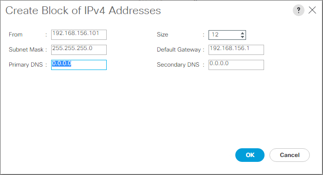
-
Click OK to create the block.
-
Click OK in the confirmation message.
Synchronize Cisco UCS to NTP
To synchronize the Cisco UCS environment to the NTP servers in the Nexus switches, complete the following steps:
-
In Cisco UCS Manager, click Admin on the left.
-
Expand All > Time Zone Management.
-
Select Time Zone.
-
In the Properties pane, select the appropriate time zone in the Time Zone menu.
-
Click Save Changes and click OK.
-
Click Add NTP Server.
-
Enter
<switch-a-ntp-ip> or <Nexus-A-mgmt-IP>and click OK. Click OK.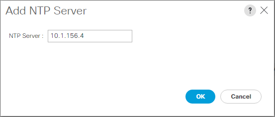
-
Click Add NTP Server.
-
Enter
<switch-b-ntp-ip>or <Nexus-B-mgmt-IP>and click OK. Click OK on the confirmation.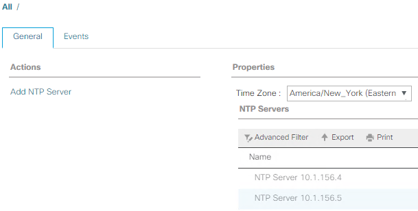
Edit chassis discovery policy
Setting the discovery policy simplifies the addition of Cisco UCS B-Series chassis and of additional fabric extenders for further Cisco UCS C-Series connectivity. To modify the chassis discovery policy, complete the following steps:
-
In Cisco UCS Manager, click Equipment on the left and select Equipment in the second list.
-
In the right pane, select the Policies tab.
-
Under Global Policies, set the Chassis/FEX Discovery Policy to match the minimum number of uplink ports that are cabled between the chassis or fabric extenders (FEXes) and the fabric interconnects.
-
Set the Link Grouping Preference to Port Channel. If the environment being setup contains a large amount of multicast traffic, set the Multicast Hardware Hash setting to Enabled.
-
Click Save Changes.
-
Click OK.
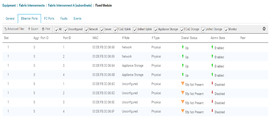
Enable server, uplink, and storage ports
To enable server and uplink ports, complete the following steps:
-
In Cisco UCS Manager, in the navigation pane, select the Equipment tab.
-
Expand Equipment > Fabric Interconnects > Fabric Interconnect A > Fixed Module.
-
Expand Ethernet Ports.
-
Select ports 1 and 2 that are connected to the Cisco Nexus 31108 switches, right-click, and select Configure as Uplink Port.
-
Click Yes to confirm the uplink ports and click OK.
-
Select ports 3 and 4 that are connected to the NetApp Storage Controllers, right-click, and select Configure as Appliance Port.
-
Click Yes to confirm the appliance ports.
-
On the Configure as Appliance Port window, click OK.
-
Click OK to confirm.
-
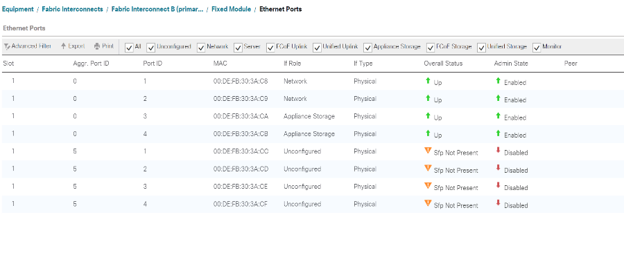
In the left pane, select Fixed Module under Fabric Interconnect A.
-
From the Ethernet Ports tab, confirm that ports have been configured correctly in the If Role column. If any port C-Series servers were configured on the Scalability port, click on it to verify port connectivity there.
-
Expand Equipment > Fabric Interconnects > Fabric Interconnect B > Fixed Module.
-
Expand Ethernet Ports.
-
Select Ethernet ports 1 and 2 that are connected to the Cisco Nexus 31108 switches, right-click, and select Configure as Uplink Port.
-
Click Yes to confirm the uplink ports and click OK.
-
Select ports 3 and 4 that are connected to the NetApp Storage Controllers, right-click, and select Configure as Appliance Port.
-
Click Yes to confirm the appliance ports.
-
On the Configure as Appliance Port window, click OK.
-
Click OK to confirm.
-
In the left pane, select Fixed Module under Fabric Interconnect B.
-
From the Ethernet Ports tab, confirm that ports have been configured correctly in the If Role column. If any port C-Series servers were configured on the Scalability port, click it to verify port connectivity there.
Create uplink port channels to Cisco Nexus 31108 switches
To configure the necessary port channels in the Cisco UCS environment, complete the following steps:
-
In Cisco UCS Manager, select the LAN tab in the navigation pane.
In this procedure, two port channels are created: one from Fabric A to both Cisco Nexus 31108 switches and one from Fabric B to both Cisco Nexus 31108 switches. If you are using standard switches, modify this procedure accordingly. If you are using 1 Gigabit Ethernet (1GbE) switches and GLC-T SFPs on the Fabric Interconnects, the interface speeds of Ethernet ports 1/1 and 1/2 in the Fabric Interconnects must be set to 1Gbps. -
Under LAN > LAN Cloud, expand the Fabric A tree.
-
Right-click Port Channels.
-
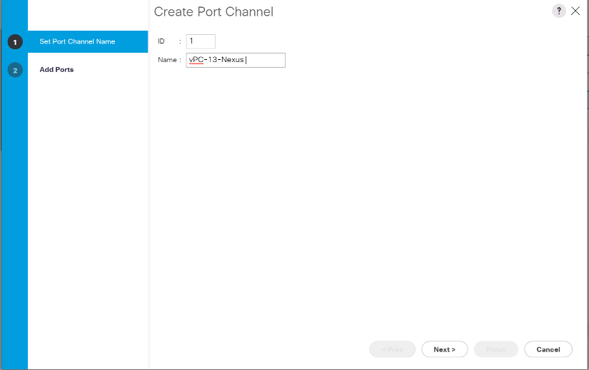
Select Create Port Channel.
-
Enter 13 as the unique ID of the port channel.
-
Enter vPC-13-Nexus as the name of the port channel.
-
Click Next.
-
Select the following ports to be added to the port channel:
-
Slot ID 1 and port 1
-
Slot ID 1 and port 2
-
-
Click >> to add the ports to the port channel.
-
Click Finish to create the port channel. Click OK.
-
Under Port Channels, select the newly created port channel.
The port channel should have an Overall Status of Up.
-
In the navigation pane, under LAN > LAN Cloud, expand the Fabric B tree.
-
Right-click Port Channels.
-
Select Create Port Channel.
-
Enter 14 as the unique ID of the port channel.
-
Enter vPC-14-Nexus as the name of the port channel. Click Next.
-
Select the following ports to be added to the port channel:
-
Slot ID 1 and port 1
-
Slot ID 1 and port 2
-
-
Click >> to add the ports to the port channel.
-
Click Finish to create the port channel. Click OK.
-
Under Port Channels, select the newly created port-channel.
-
The port channel should have an Overall Status of Up.
Create an organization (optional)
Organizations are used to organizing resources and restricting access to various groups within the IT organization, thereby enabling multitenancy of the compute resources.
|
|
Although this document does not assume the use of organizations, this procedure provides instructions for creating one. |
To configure an organization in the Cisco UCS environment, complete the following steps:
-
In Cisco UCS Manager, from the New menu in the toolbar at the top of the window, select Create Organization.
-
Enter a name for the organization.
-
Optional: Enter a description for the organization. Click OK.
-
Click OK in the confirmation message.
Configure storage appliance ports and storage VLANs
To configure the storage appliance ports and storage VLANs, complete the following steps:
-
In the Cisco UCS Manager, select the LAN tab.
-
Expand the Appliances cloud.
-
Right-click VLANs under Appliances Cloud.
-
Select Create VLANs.
-
Enter NFS-VLAN as the name for the Infrastructure NFS VLAN.
-
Leave Common/Global selected.
-
Enter
<<var_nfs_vlan_id>>for the VLAN ID. -
Leave Sharing Type set to None.
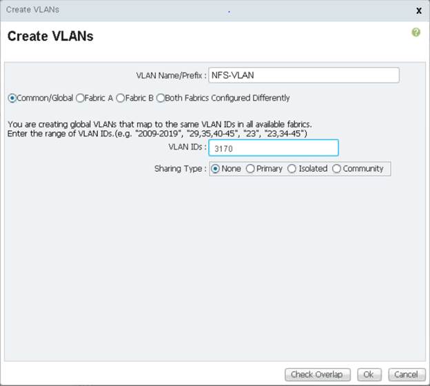
-
Click OK, and then click OK again to create the VLAN.
-
Right-click VLANs under Appliances Cloud.
-
Select Create VLANs.
-
Enter iSCSI-A-VLAN as the name for the Infrastructure iSCSI Fabric A VLAN.
-
Leave Common/Global selected.
-
Enter
<<var_iscsi-a_vlan_id>>for the VLAN ID. -
Click OK, and then click OK again to create the VLAN.
-
Right-click VLANs under Appliances Cloud.
-
Select Create VLANs.
-
Enter iSCSI-B-VLAN as the name for the Infrastructure iSCSI Fabric B VLAN.
-
Leave Common/Global selected.
-
Enter
<<var_iscsi-b_vlan_id>>for the VLAN ID. -
Click OK, and then click OK again to create the VLAN.
-
Right-click VLANs under Appliances Cloud.
-
Select Create VLANs.
-
Enter Native-VLAN as the name for the Native VLAN.
-
Leave Common/Global selected.
-
Enter
<<var_native_vlan_id>>for the VLAN ID. -
Click OK, and then click OK again to create the VLAN.
-
In the navigation pane, under LAN > Policies, expand Appliances and right-click Network Control Policies.
-
Select Create Network Control Policy.
-
Name the policy
Enable_CDP_LLPDand select Enabled next to CDP. -
Enable the Transmit and Receive features for LLDP.
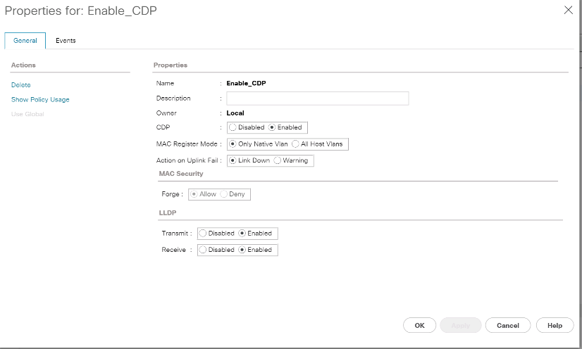
-
Click OK and then click OK again to create the policy.
-
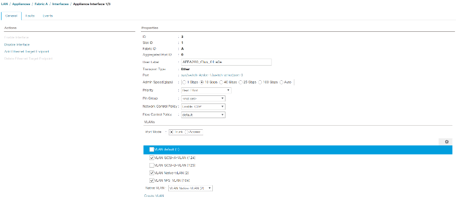
In the navigation pane, under LAN > Appliances Cloud, expand the Fabric A tree.
-
Expand Interfaces.
-
Select Appliance Interface 1/3.
-
In the User Label field, put in information indicating the storage controller port, such as
<storage_controller_01_name>:e0e. Click Save Changes and OK. -
Select the Enable_CDP Network Control Policy and select Save Changes and OK.
-
Under VLANs, select the iSCSI-A-VLAN, NFS VLAN, and Native VLAN. Set the Native-VLAN as the Native VLAN. Clear the default VLAN selection.
-
Click Save Changes and OK.
-
Select Appliance Interface 1/4 under Fabric A.
-
In the User Label field, put in information indicating the storage controller port, such as
<storage_controller_02_name>:e0e. Click Save Changes and OK. -
Select the Enable_CDP Network Control Policy and select Save Changes and OK.
-
Under VLANs, select the iSCSI-A-VLAN, NFS VLAN, and Native VLAN.
-
Set the Native-VLAN as the Native VLAN.
-
Clear the default VLAN selection.
-
Click Save Changes and OK.
-
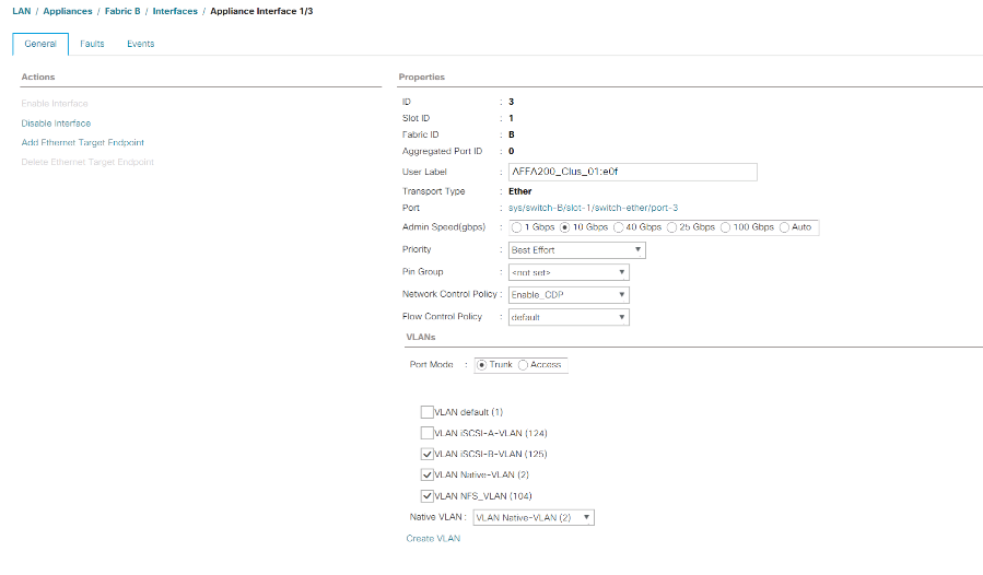
In the navigation pane, under LAN > Appliances Cloud, expand the Fabric B tree.
-
Expand Interfaces.
-
Select Appliance Interface 1/3.
-
In the User Label field, put in information indicating the storage controller port, such as
<storage_controller_01_name>:e0f. Click Save Changes and OK. -
Select the Enable_CDP Network Control Policy and select Save Changes and OK.
-
Under VLANs, select the iSCSI-B-VLAN, NFS VLAN, and Native VLAN. Set the Native-VLAN as the Native VLAN. Unselect the default VLAN.
-
Click Save Changes and OK.
-
Select Appliance Interface 1/4 under Fabric B.
-
In the User Label field, put in information indicating the storage controller port, such as
<storage_controller_02_name>:e0f. Click Save Changes and OK. -
Select the Enable_CDP Network Control Policy and select Save Changes and OK.
-
Under VLANs, select the iSCSI-B-VLAN, NFS VLAN, and Native VLAN. Set the Native-VLAN as the Native VLAN. Unselect the default VLAN.
-
Click Save Changes and OK.
Set jumbo frames in Cisco UCS fabric
To configure jumbo frames and enable quality of service in the Cisco UCS fabric, complete the following steps:
-
In Cisco UCS Manager, in the navigation pane, click the LAN tab.
-
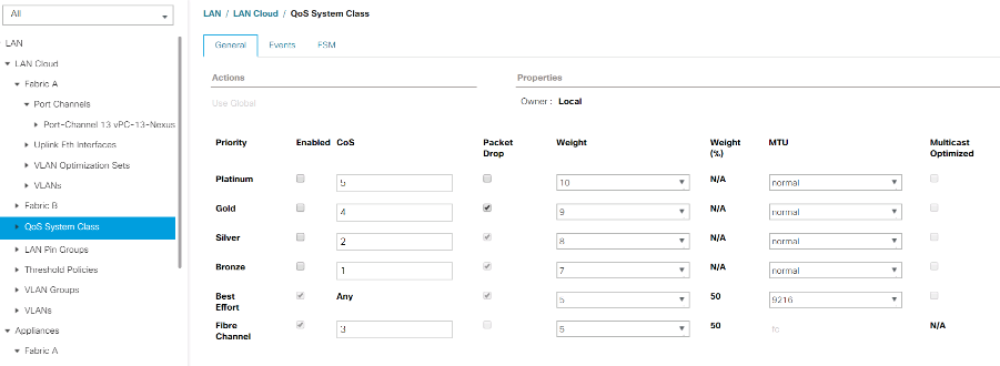
Select LAN > LAN Cloud > QoS System Class.
-
In the right pane, click the General tab.
-
On the Best Effort row, enter 9216 in the box under the MTU column.
-
Click Save Changes.
-
Click OK.
Acknowledge Cisco UCS chassis
To acknowledge all Cisco UCS chassis, complete the following steps:
-
In Cisco UCS Manager, select the Equipment tab, then Expand the Equipment tab on the right.
-
Expand Equipment > Chassis.
-
In the Actions for Chassis 1, select Acknowledge Chassis.
-
Click OK and then click OK to complete acknowledging the chassis.
-
Click Close to close the Properties window.
Load Cisco UCS 4.0(1b) firmware images
To upgrade the Cisco UCS Manager software and the Cisco UCS Fabric Interconnect software to version 4.0(1b) refer to Cisco UCS Manager Install and Upgrade Guides.
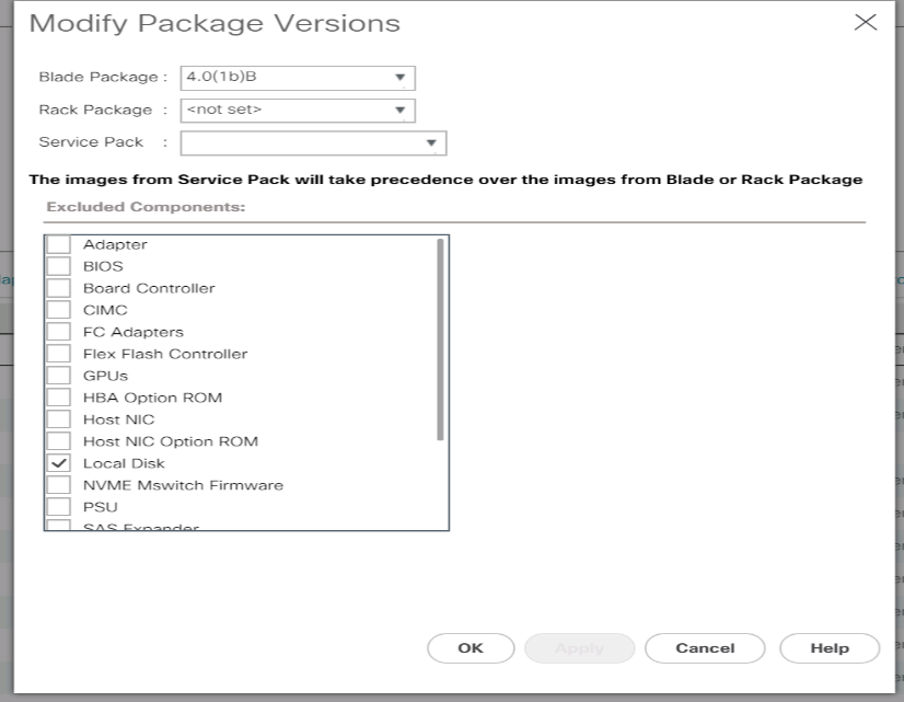
Create host firmware package
Firmware management policies allow the administrator to select the corresponding packages for a given server configuration. These policies often include packages for adapter, BIOS, board controller, FC adapters, host bus adapter (HBA) option ROM, and storage controller properties.
To create a firmware management policy for a given server configuration in the Cisco UCS environment, complete the following steps:
-
In Cisco UCS Manager, click Servers on the left.
-
Select Policies > root.
-
Expand Host Firmware Packages.
-
Select default.
-
In the Actions pane, select Modify Package Versions.
-
Select the version 4.0(1b) for both the Blade Packages.
-
Click OK then OK again to modify the host firmware package.
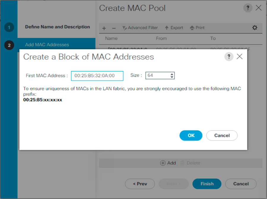
Create MAC address pools
To configure the necessary MAC address pools for the Cisco UCS environment, complete the following steps:
-
In Cisco UCS Manager, click LAN on the left.
-
Select Pools > root.
In this procedure, two MAC address pools are created, one for each switching fabric.
-
Right-click MAC Pools under the root organization.
-
Select Create MAC Pool to create the MAC address pool.
-
Enter MAC-Pool-A as the name of the MAC pool.
-
Optional: Enter a description for the MAC pool.
-
Select Sequential as the option for Assignment Order. Click Next.
-
Click Add.
-
Specify a starting MAC address.
For the FlexPod solution, the recommendation is to place 0A in the next-to-last octet of the starting MAC address to identify all of the MAC addresses as fabric A addresses. In our example, we have carried forward the example of also embedding the Cisco UCS domain number information giving us 00:25:B5:32:0A:00 as our first MAC address. -
Specify a size for the MAC address pool that is sufficient to support the available blade or server resources. Click OK.
-
Click Finish.
-
In the confirmation message, click OK.
-
Right-click MAC Pools under the root organization.
-
Select Create MAC Pool to create the MAC address pool.
-
Enter MAC-Pool-B as the name of the MAC pool.
-
Optional: Enter a description for the MAC pool.
-
Select Sequential as the option for Assignment Order. Click Next.
-
Click Add.
-
Specify a starting MAC address.
For the FlexPod solution, it is recommended to place 0B in the next to last octet of the starting MAC address to identify all the MAC addresses in this pool as fabric B addresses. Once again, we have carried forward in our example of also embedding the Cisco UCS domain number information giving us 00:25:B5:32:0B:00 as our first MAC address. -
Specify a size for the MAC address pool that is sufficient to support the available blade or server resources. Click OK.
-
Click Finish.
-
In the confirmation message, click OK.
Create iSCSI IQN pool
To configure the necessary IQN pools for the Cisco UCS environment, complete the following steps:
-
In Cisco UCS Manager, click SAN on the left.
-
Select Pools > root.
-
Right- click IQN Pools.
-
Select Create IQN Suffix Pool to create the IQN pool.
-
Enter IQN-Pool for the name of the IQN pool.
-
Optional: Enter a description for the IQN pool.
-
Enter
iqn.1992-08.com.ciscoas the prefix. -
Select Sequential for Assignment Order. Click Next.
-
Click Add.
-
Enter
ucs-hostas the suffix.
If multiple Cisco UCS domains are being used, a more specific IQN suffix might need to be used. -
Enter 1 in the From field.
-
Specify the size of the IQN block sufficient to support the available server resources. Click OK.
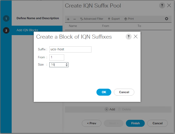
-
Click Finish.
Create iSCSI initiator IP address pools
To configure the necessary IP pools iSCSI boot for the Cisco UCS environment, complete the following steps:
-
In Cisco UCS Manager, click LAN on the left.
-
Select Pools > root.
-
Right-click IP Pools.
-
Select Create IP Pool.
-
Enter iSCSI-IP-Pool-A as the name of IP pool.
-
Optional: Enter a description for the IP pool.
-
Select Sequential for the assignment order. Click Next.
-
Click Add to add a block of IP address.
-
In the From field, enter the beginning of the range to assign as iSCSI IP addresses.
-
Set the size to enough addresses to accommodate the servers. Click OK.
-
Click Next.
-
Click Finish.
-
Right-click IP Pools.
-
Select Create IP Pool.
-
Enter iSCSI-IP-Pool-B as the name of IP pool.
-
Optional: Enter a description for the IP pool.
-
Select Sequential for the assignment order. Click Next.
-
Click Add to add a block of IP address.
-
In the From field, enter the beginning of the range to assign as iSCSI IP addresses.
-
Set the size to enough addresses to accommodate the servers. Click OK.
-
Click Next.
-
Click Finish.
Create UUID suffix pool
To configure the necessary universally unique identifier (UUID) suffix pool for the Cisco UCS environment, complete the following steps:
-
In Cisco UCS Manager, click Servers on the left.
-
Select Pools > root.
-
Right-click UUID Suffix Pools.
-
Select Create UUID Suffix Pool.
-
Enter UUID-Pool as the name of the UUID suffix pool.
-
Optional: Enter a description for the UUID suffix pool.
-
Keep the prefix at the derived option.
-
Select Sequential for the Assignment Order.
-
Click Next.
-
Click Add to add a block of UUIDs.
-
Keep the From field at the default setting.
-
Specify a size for the UUID block that is sufficient to support the available blade or server resources. Click OK.
-
Click Finish.
-
Click OK.
Create server pool
To configure the necessary server pool for the Cisco UCS environment, complete the following steps:
|
|
Consider creating unique server pools to achieve the granularity that is required in your environment. |
-
In Cisco UCS Manager, click Servers on the left.
-
Select Pools > root.
-
Right-click Server Pools.
-
Select Create Server Pool.
-
Enter `Infra-Pool `as the name of the server pool.
-
Optional: Enter a description for the server pool. Click Next.
-
Select two (or more) servers to be used for the VMware management cluster and click >> to add them to the `Infra-Pool `server pool.
-
Click Finish.
-
Click OK.
Create Network Control Policy for Cisco Discovery Protocol and Link Layer Discovery Protocol
To create a Network Control Policy for Cisco Discovery Protocol (CDP) and Link Layer Discovery Protocol (LLDP), complete the following steps:
-
In Cisco UCS Manager, click LAN on the left.
-
Select Policies > root.
-
Right-click Network Control Policies.
-
Select Create Network Control Policy.
-
Enter Enable-CDP-LLDP policy name.
-
For CDP, select the Enabled option.
-
For LLDP, scroll down and select Enabled for both Transmit and Receive.
-
Click OK to create the network control policy. Click OK.
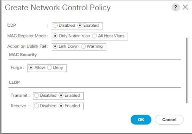
Create power control policy
To create a power control policy for the Cisco UCS environment, complete the following steps:
-
In Cisco UCS Manager, click Servers tab on the left.
-
Select Policies > root.
-
Right-click Power Control Policies.
-
Select Create Power Control Policy.
-
Enter No-Power-Cap as the power control policy name.
-
Change the power capping setting to No Cap.
-
Click OK to create the power control policy. Click OK.
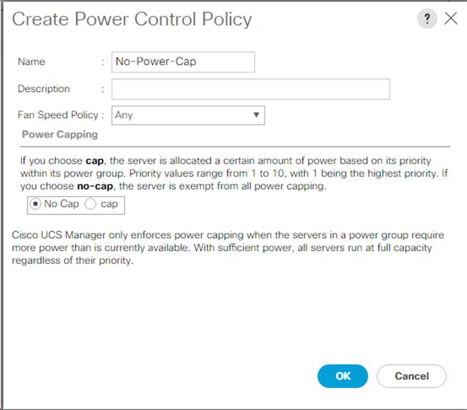
Create server pool qualification policy (Optional)
To create an optional server pool qualification policy for the Cisco UCS environment, complete the following steps:
|
|
This example creates a policy for Cisco UCS B-Series servers with the Intel E2660 v4 Xeon Broadwell processors. |
-
In Cisco UCS Manager, click Servers on the left.
-
Select Policies > root.
-
Select Server Pool Policy Qualifications.
-
Select Create Server Pool Policy Qualification or Add.
-
Name the policy Intel.
-
Select Create CPU/Cores Qualifications.
-
Select Xeon for the Processor/Architecture.
-
Enter
<UCS-CPU- PID>as the process ID (PID). -
Click OK to create the CPU/Core qualification.
-
Click OK to create the policy, and then click OK for the confirmation.
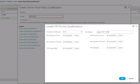
Create server BIOS policy
To create a server BIOS policy for the Cisco UCS environment, complete the following steps:
-
In Cisco UCS Manager, click Servers on the left.
-
Select Policies > root.
-
Right-click BIOS Policies.
-
Select Create BIOS Policy.
-
Enter VM-Host as the BIOS policy name.
-
Change the Quiet Boot setting to disabled.
-
Change Consistent Device Naming to enabled.
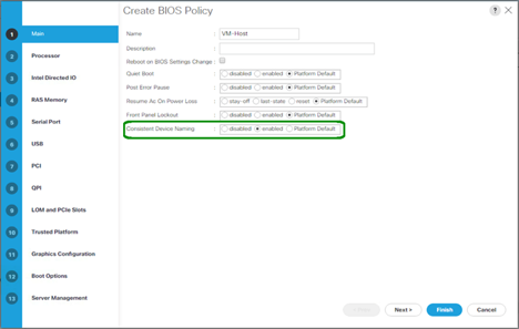
-
Select the Processor tab and set the following parameters:
-
Processor C State: disabled
-
Processor C1E: disabled
-
Processor C3 Report: disabled
-
Processor C7 Report: disabled
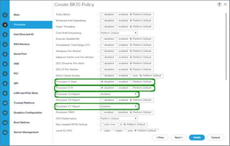
-
-
Scroll down to the remaining Processor options and set the following parameters:
-
Energy Performance: performance
-
Frequency Floor Override: enabled
-
DRAM Clock Throttling: performance
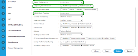
-
-
Click RAS Memory and set the following parameters:
-
LV DDR Mode: performance mode
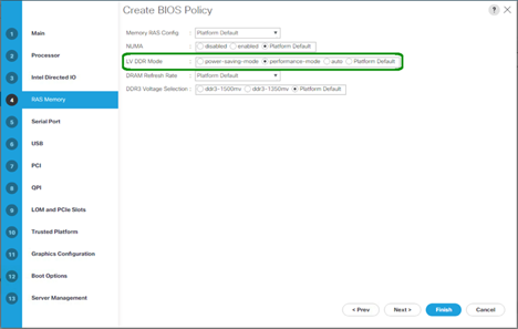
-
-
Click Finish to create the BIOS policy.
-
Click OK.
Update the default maintenance policy
To update the default Maintenance Policy, complete the following steps:
-
In Cisco UCS Manager, click Servers on the left.
-
Select Policies > root.
-
Select Maintenance Policies > default.
-
Change the Reboot Policy to User Ack.
-
Select On Next Boot to delegate maintenance windows to server administrators.
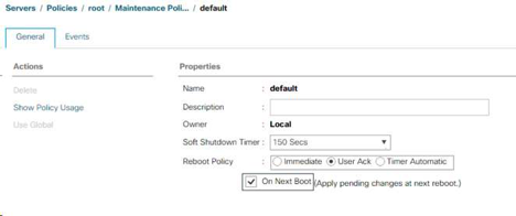
-
Click Save Changes.
-
Click OK to accept the change.
Create vNIC templates
To create multiple virtual network interface card (vNIC) templates for the Cisco UCS environment, complete the procedures described in this section.
|
|
A total of four vNIC templates are created. |
Create infrastructure vNICs
To create an infrastructure vNIC, complete the following steps:
-
In Cisco UCS Manager, click LAN on the left.
-
Select Policies > root.
-
Right-click vNIC Templates.
-
Select Create vNIC Template.
-
Enter
Site-XX-vNIC_Aas the vNIC template name. -
Select updating-template as the Template Type.
-
For Fabric ID, select Fabric A.
-
Ensure that the Enable Failover option is not selected.
-
Select Primary Template for Redundancy Type.
-
Leave the Peer Redundancy Template set to
<not set>. -
Under Target, make sure that only the Adapter option is selected.
-
Set
Native-VLANas the native VLAN. -
Select vNIC Name for the CDN Source.
-
For MTU, enter 9000.
-
Under Permitted VLANs, select
Native-VLAN, Site-XX-IB-MGMT, Site-XX-NFS, Site-XX-VM-Traffic, and Site-XX-vMotion. Use the Ctrl key to make this multiple selection. -
Click Select. These VLANs should now appear under Selected VLANs.
-
In the MAC Pool list, select
MAC_Pool_A. -
In the Network Control Policy list, select Pool-A.
-
In the Network Control Policy list, select Enable-CDP-LLDP.
-
Click OK to create the vNIC template.
-
Click OK.
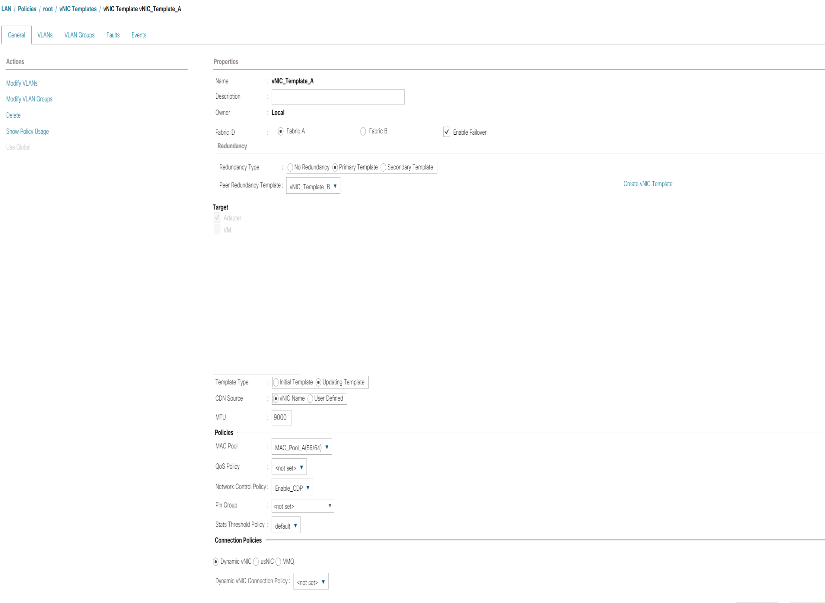
To create the secondary redundancy template Infra-B, complete the following steps:
-
In Cisco UCS Manager, click LAN on the left.
-
Select Policies > root.
-
Right-click vNIC Templates.
-
Select Create vNIC Template.
-
Enter `Site-XX-vNIC_B `as the vNIC template name.
-
Select updating-template as the Template Type.
-
For Fabric ID, select Fabric B.
-
Select the Enable Failover option.
Selecting Failover is a critical step to improve link failover time by handling it at the hardware level, and to guard against any potential for NIC failure not being detected by the virtual switch. -
Select Primary Template for Redundancy Type.
-
Leave the Peer Redundancy Template set to
vNIC_Template_A. -
Under Target, make sure that only the Adapter option is selected.
-
Set
Native-VLANas the native VLAN. -
Select vNIC Name for the CDN Source.
-
For MTU, enter
9000. -
Under Permitted VLANs, select
Native-VLAN, Site-XX-IB-MGMT, Site-XX-NFS, Site-XX-VM-Traffic, and Site-XX-vMotion. Use the Ctrl key to make this multiple selection. -
Click Select. These VLANs should now appear under Selected VLANs.
-
In the MAC Pool list, select
MAC_Pool_B. -
In the Network Control Policy list, select Pool-B.
-
In the Network Control Policy list, select Enable-CDP-LLDP.
-
Click OK to create the vNIC template.
-
Click OK.
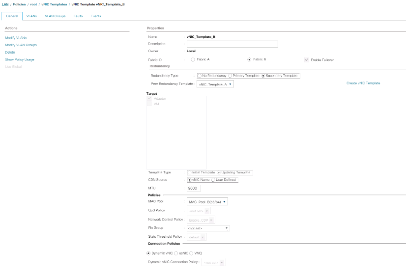
Create iSCSI vNICs
To create iSCSI vNICs, complete the following steps:
-
Select LAN on the left.
-
Select Policies > root.
-
Right-click vNIC Templates.
-
Select Create vNIC Template.
-
Enter
Site- 01-iSCSI_Aas the vNIC template name. -
Select Fabric A. Do not select the Enable Failover option.
-
Leave Redundancy Type set at No Redundancy.
-
Under Target, make sure that only the Adapter option is selected.
-
Select Updating Template for Template Type.
-
Under VLANs, select only Site- 01-iSCSI_A_VLAN.
-
Select Site- 01-iSCSI_A_VLAN as the native VLAN.
-
Leave vNIC Name set for the CDN Source.
-
Under MTU, enter 9000.
-
From the MAC Pool list, select MAC-Pool-A.
-
From the Network Control Policy list, select Enable-CDP-LLDP.
-
Click OK to complete creating the vNIC template.
-
Click OK.
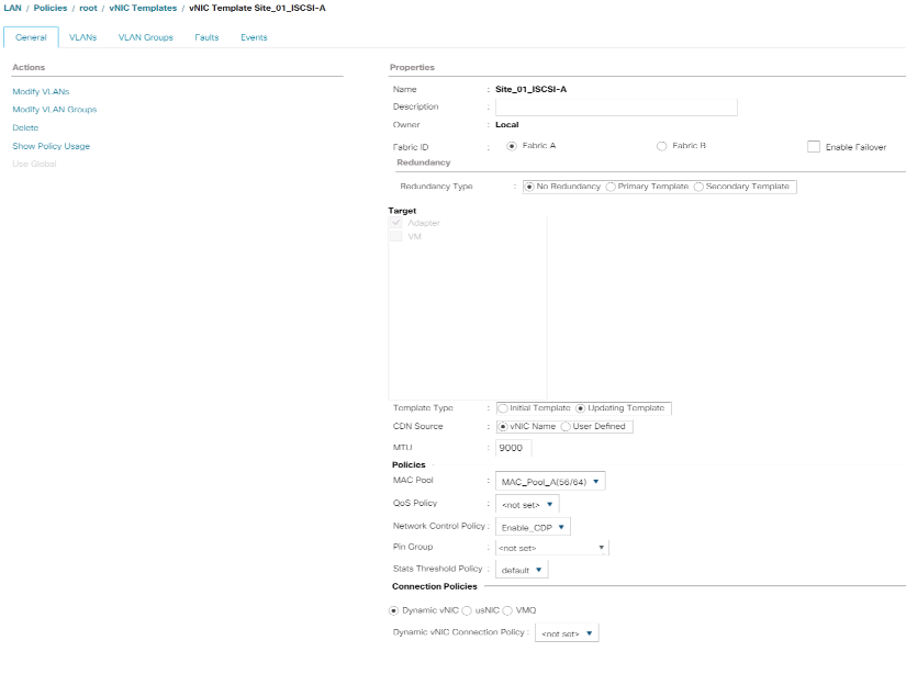
-
Select LAN on the left.
-
Select Policies > root.
-
Right-click vNIC Templates.
-
Select Create vNIC Template.
-
Enter
Site- 01-iSCSI_Bas the vNIC template name. -
Select Fabric B. Do not select the Enable Failover option.
-
Leave Redundancy Type set at No Redundancy.
-
Under Target, make sure that only the Adapter option is selected.
-
Select Updating Template for Template Type.
-
Under VLANs, select only
Site- 01-iSCSI_B_VLAN. -
Select
Site- 01-iSCSI_B_VLANas the native VLAN. -
Leave vNIC Name set for the CDN Source.
-
Under MTU, enter 9000.
-
From the MAC Pool list, select
MAC-Pool-B. -
From the Network Control Policy list, select
Enable-CDP-LLDP. -
Click OK to complete creating the vNIC template.
-
Click OK.
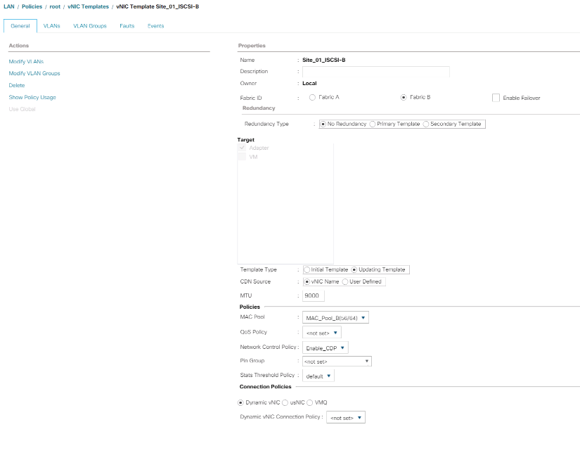
Create LAN connectivity policy for iSCSI boot
This procedure applies to a Cisco UCS environment in which two iSCSI LIFs are on cluster node 1 (iscsi_lif01a and iscsi_lif01b) and two iSCSI LIFs are on cluster node 2 (iscsi_lif02a and iscsi_lif02b). Also, it is assumed that the A LIFs are connected to Fabric A (Cisco UCS 6324 A) and the B LIFs are connected to Fabric B (Cisco UCS 6324 B).
To configure the necessary Infrastructure LAN Connectivity Policy, complete the following steps:
-
In Cisco UCS Manager, click LAN on the left.
-
Select LAN > Policies > root.
-
Right-click LAN Connectivity Policies.
-
Select Create LAN Connectivity Policy.
-
Enter
Site-XX-Fabric-Aas the name of the policy. -
Click the upper Add option to add a vNIC.
-
In the Create vNIC dialog box, enter
Site-01-vNIC-Aas the name of the vNIC. -
Select the Use vNIC Template option.
-
In the vNIC Template list, select
vNIC_Template_A. -
From the Adapter Policy drop-down list, select VMWare.
-
Click OK to add this vNIC to the policy.
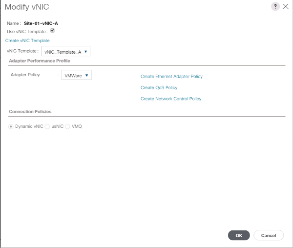
-
Click the upper Add option to add a vNIC.
-
In the Create vNIC dialog box, enter
Site-01-vNIC-Bas the name of the vNIC. -
Select the Use vNIC Template option.
-
In the vNIC Template list, select
vNIC_Template_B. -
From the Adapter Policy drop-down list, select VMWare.
-
Click OK to add this vNIC to the policy.
-
Click the upper Add option to add a vNIC.
-
In the Create vNIC dialog box, enter
Site-01- iSCSI-Aas the name of the vNIC. -
Select the Use vNIC Template option.
-
In the vNIC Template list, select
Site-01-iSCSI-A. -
From the Adapter Policy drop-down list, select VMWare.
-
Click OK to add this vNIC to the policy.
-
Click the upper Add option to add a vNIC.
-
In the Create vNIC dialog box, enter
Site-01-iSCSI-Bas the name of the vNIC. -
Select the Use vNIC Template option.
-
In the vNIC Template list, select
Site-01-iSCSI-B. -
From the Adapter Policy drop-down list, select VMWare.
-
Click OK to add this vNIC to the policy.
-
Expand the Add iSCSI vNICs option.
-
Click the Lower Add option in the Add iSCSI vNICs space to add the iSCSI vNIC.
-
In the Create iSCSI vNIC dialog box, enter
Site-01-iSCSI-Aas the name of the vNIC. -
Select the Overlay vNIC as
Site-01-iSCSI-A. -
Leave the iSCSI Adapter Policy option to Not Set.
-
Select the VLAN as
Site-01-iSCSI-Site-A(native). -
Select None (used by default) as the MAC address assignment.
-
Click OK to add the iSCSI vNIC to the policy.
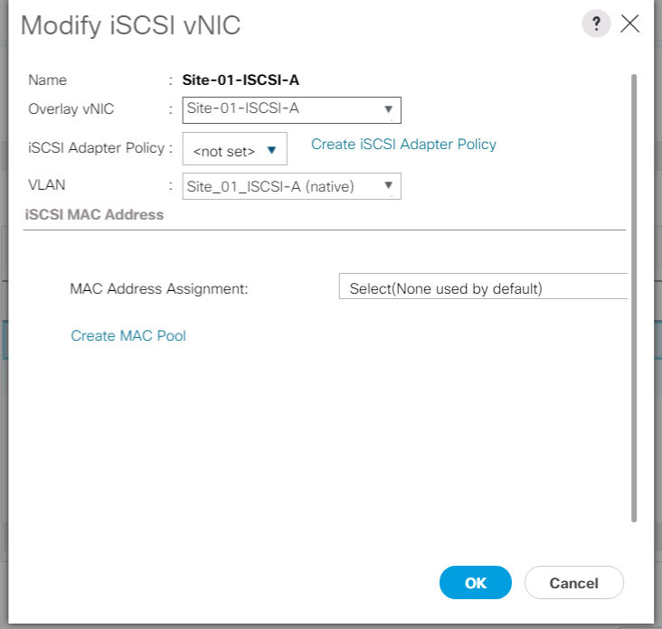
-
Click the Lower Add option in the Add iSCSI vNICs space to add the iSCSI vNIC.
-
In the Create iSCSI vNIC dialog box, enter
Site-01-iSCSI-Bas the name of the vNIC. -
Select the Overlay vNIC as Site-01-iSCSI-B.
-
Leave the iSCSI Adapter Policy option to Not Set.
-
Select the VLAN as
Site-01-iSCSI-Site-B(native). -
Select None(used by default) as the MAC Address Assignment.
-
Click OK to add the iSCSI vNIC to the policy.
-
Click Save Changes.
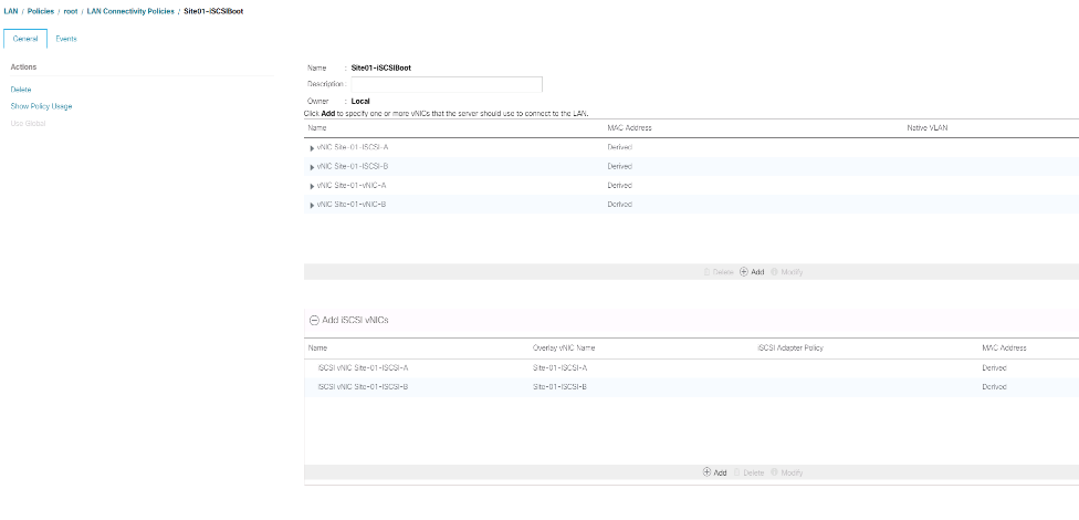
Create vMedia policy for VMware ESXi 6.7U1 install boot
In the NetApp Data ONTAP setup steps an HTTP web server is required, which is used for hosting NetApp Data ONTAP as well as VMware software. The vMedia Policy created here maps the VMware ESXi 6. 7U1 ISO to the Cisco UCS server in order to boot the ESXi installation. To create this policy, complete the following steps:
-
In Cisco UCS Manager, select Servers on the left.
-
Select Policies > root.
-
Select vMedia Policies.
-
Click Add to create new vMedia Policy.
-
Name the policy ESXi-6.7U1-HTTP.
-
Enter Mounts ISO for ESXi 6.7U1 in the Description field.
-
Select Yes for Retry on Mount failure.
-
Click Add.
-
Name the mount ESXi-6.7U1-HTTP.
-
Select the CDD Device Type.
-
Select the HTTP Protocol.
-
Enter the IP Address of the web server.
The DNS server IPs were not entered into the KVM IP earlier, therefore, it is necessary to enter the IP of the web server instead of the hostname. -
Enter
VMware-VMvisor-Installer-6.7.0.update01-10302608.x86_64.isoas the Remote File name.This VMware ESXi 6.7U1 ISO can be downloaded from Broadcom support portal.
-
Enter the web server path to the ISO file in the Remote Path field.
-
Click OK to create the vMedia Mount.
-
Click OK then OK again to complete creating the vMedia Policy.
For any new servers added to the Cisco UCS environment the vMedia service profile template can be used to install the ESXi host. On first boot, the host boots into the ESXi installer since the SAN mounted disk is empty. After ESXi is installed, the vMedia is not referenced as long as the boot disk is accessible.
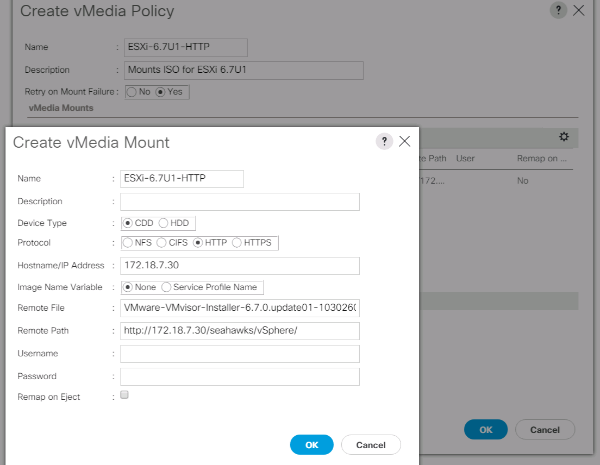
Create iSCSI boot policy
The procedure in this section applies to a Cisco UCS environment in which two iSCSI logical interfaces (LIFs) are on cluster node 1 (iscsi_lif01a and iscsi_lif01b) and two iSCSI LIFs are on cluster node 2 (iscsi_lif02a and iscsi_lif02b). Also, it is assumed that the A LIFs are connected to Fabric A (Cisco UCS Fabric Interconnect A) and the B LIFs are connected to Fabric B (Cisco UCS Fabric Interconnect B).
|
|
One boot policy is configured in this procedure. The policy configures the primary target to be iscsi_lif01a.
|
To create a boot policy for the Cisco UCS environment, complete the following steps:
-
In Cisco UCS Manager, click Servers on the left.
-
Select Policies > root.
-
Right-click Boot Policies.
-
Select Create Boot Policy.
-
Enter
Site-01-Fabric-Aas the name of the boot policy. -
Optional: Enter a description for the boot policy.
-
Keep the Reboot on Boot Order Change option cleared.
-
Boot Mode is Legacy.
-
Expand the Local Devices drop-down menu and select Add Remote CD/DVD.
-
Expand the iSCSI vNICs drop-down menu and select Add iSCSI Boot.
-
In the Add iSCSI Boot dialog box, enter
Site-01-iSCSI-A. Click OK. -
Select Add iSCSI Boot.
-
In the Add iSCSI Boot dialog box, enter
Site-01-iSCSI-B. Click OK. -
Click OK to create the policy.
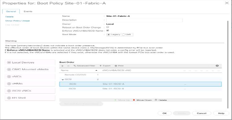
Create service profile template
In this procedure, one service profile template for Infrastructure ESXi hosts is created for Fabric A boot.
To create the service profile template, complete the following steps:
-
In Cisco UCS Manager, click Servers on the left.
-
Select Service Profile Templates > root.
-
Right-click root.
-
Select Create Service Profile Template to open the Create Service Profile Template wizard.
-
Enter
VM-Host-Infra-iSCSI-Aas the name of the service profile template. This service profile template is configured to boot from storage node 1 on fabric A. -
Select the Updating Template option.
-
Under UUID, select
UUID_Poolas the UUID pool. Click Next.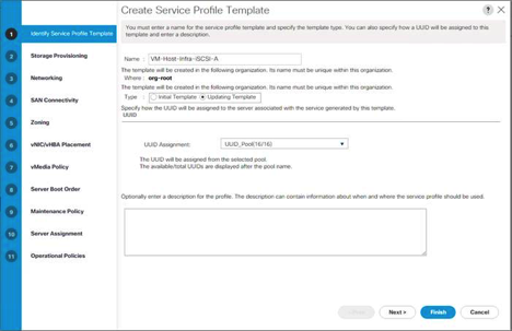
Configure storage provisioning
To configure storage provisioning, complete the following steps:
-
If you have servers with no physical disks, click Local Disk Configuration Policy and select the SAN Boot Local Storage Policy. Otherwise, select the default Local Storage Policy.
-
Click Next.
Configure networking options
To configure the networking options, complete the following steps:
-
Keep the default setting for Dynamic vNIC Connection Policy.
-
Select the Use Connectivity Policy option to configure the LAN connectivity.
-
Select iSCSI-Boot from the LAN Connectivity Policy drop-down menu.
-
Select
IQN_Poolin Initiator Name Assignment. Click Next.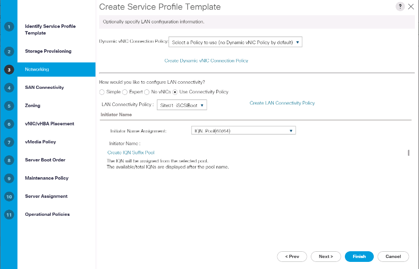
Configure SAN connectivity
To configure SAN connectivity, complete the following steps:
-
For the vHBAs, select No for the How Would you Like to Configure SAN Connectivity? option.
-
Click Next.
Configure zoning
To configure zoning, simply click Next.
Configure vNIC/HBA placement
To configure vNIC/HBA placement, complete the following steps:
-
From the Select Placement drop-down list, leave the placement policy as Let System Perform Placement.
-
Click Next.
Configure vMedia policy
To configure the vMedia policy, complete the following steps:
-
Do not select a vMedia Policy.
-
Click Next.
Configure server boot order
To configure the server boot order, complete the following steps:
-
Select
Boot-Fabric-Afor Boot Policy.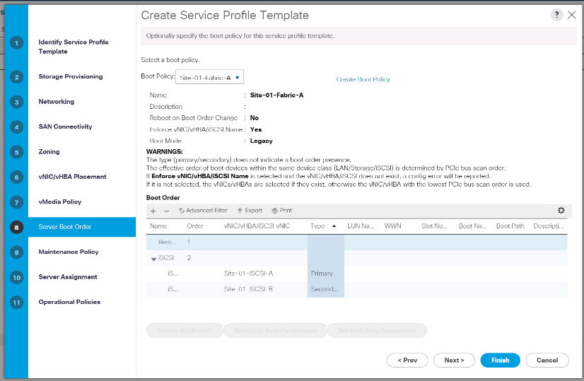
-
In the Boor order, select
Site-01- iSCSI-A. -
Click Set iSCSI Boot Parameters.
-
In the Set iSCSI Boot Parameters dialog box, leave the Authentication Profile option to Not Set unless you have independently created one appropriate for your environment.
-
Leave the Initiator Name Assignment dialog box Not Set to use the single Service Profile Initiator Name defined in the previous steps.
-
Set
iSCSI_IP_Pool_Aas the Initiator IP address Policy. -
Select iSCSI Static Target Interface option.
-
Click Add.
-
Enter the iSCSI target name. To get the iSCSI target name of Infra-SVM, log in into storage cluster management interface and run the
iscsi showcommand.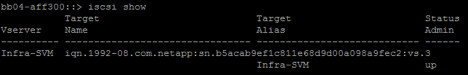
-
Enter the IP address of
iscsi_lif_02afor the IPv4 Address field.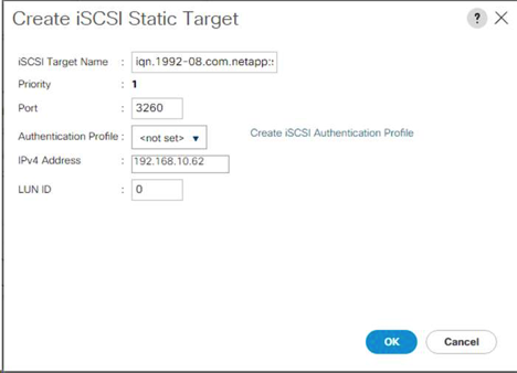
-
Click OK to add the iSCSI static target.
-
Click Add.
-
Enter the iSCSI target name.
-
Enter the IP address of
iscsi_lif_01afor the IPv4 Address field.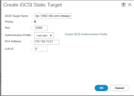
-
Click OK to add the iSCSI static target.
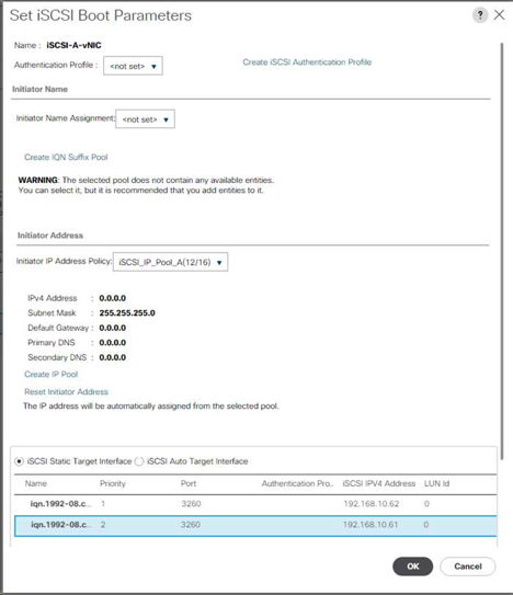
The target IPs were put in with the storage node 02 IP first and the storage node 01 IP second. This is assuming the boot LUN is on node 01. The host boots by using the path to node 01 if the order in this procedure is used. -
In the Boot order, select iSCSI-B-vNIC.
-
Click Set iSCSI Boot Parameters.
-
In the Set iSCSI Boot Parameters dialog box, leave the Authentication Profile option as Not Set unless you have independently created one appropriate to your environment.
-
Leave the Initiator Name Assignment dialog box Not Set to use the single Service Profile Initiator Name defined in the previous steps.
-
Set
iSCSI_IP_Pool_Bas the initiator IP address policy. -
Select the iSCSI Static Target Interface option.
-
Click Add.
-
Enter the iSCSI target name. To get the iSCSI target name of Infra-SVM, log in into storage cluster management interface and run the
iscsi showcommand. -
Enter the IP address of
iscsi_lif_02bfor the IPv4 Address field.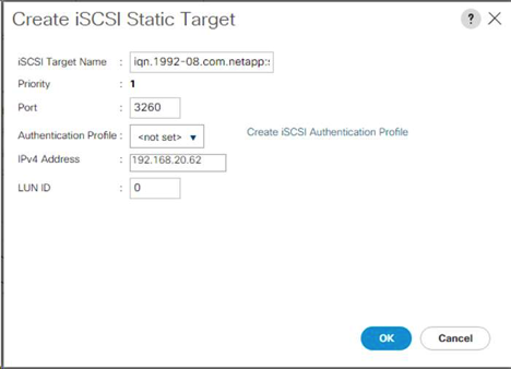
-
Click OK to add the iSCSI static target.
-
Click Add.
-
Enter the iSCSI target name.
-
Enter the IP address of
iscsi_lif_01bfor the IPv4 Address field.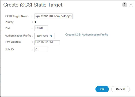
-
Click OK to add the iSCSI static target.
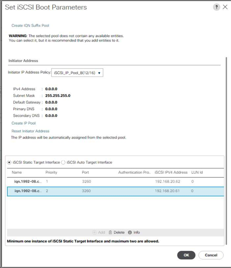
-
Click Next.
Configure maintenance policy
To configure the maintenance policy, complete the following steps:
-
Change the maintenance policy to default.
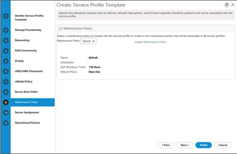
-
Click Next.
Configure server assignment
To configure the server assignment, complete the following steps:
-
In the Pool Assignment list, select Infra-Pool.
-
Select Down as the power state to be applied when the profile is associated with the server.
-
Expand Firmware Management at the bottom of the page and select the default policy.
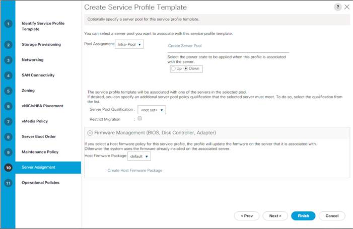
-
Click Next.
Configure operational policies
To configure the operational policies, complete the following steps:
-
From the BIOS Policy drop-down list, select VM-Host.
-
Expand Power Control Policy Configuration and select No-Power-Cap from the Power Control Policy drop-down list.
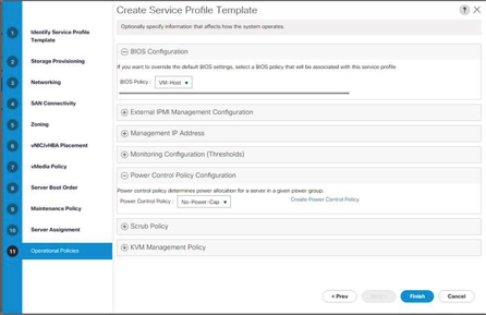
-
Click Finish to create the service profile template.
-
Click OK in the confirmation message.
Create vMedia-enabled service profile template
To create a service profile template with vMedia enabled, complete the following steps:
-
Connect to UCS Manager and click Servers on the left.
-
Select Service Profile Templates > root > Service Template VM-Host-Infra-iSCSI-A.
-
Right-click VM-Host-Infra-iSCSI-A and select Create a Clone.
-
Name the clone
VM-Host-Infra-iSCSI-A-vM. -
Select the newly created VM-Host-Infra-iSCSI-A-vM and select the vMedia Policy tab on the right.
-
Click Modify vMedia Policy.
-
Select the ESXi-6. 7U1-HTTP vMedia Policy and click OK.
-
Click OK to confirm.
Create service profiles
To create service profiles from the service profile template, complete the following steps:
-
Connect to Cisco UCS Manager and click Servers on the left.
-
Expand Servers > Service Profile Templates > root > Service Template <name>.
-
In Actions, click Create Service Profile from Template and compete the following steps:
-
Enter
Site- 01-Infra-0as the naming prefix. -
Enter
2as the number of instances to create. -
Select root as the org.
-
Click OK to create the service profiles.
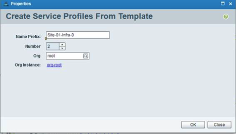
-
-
Click OK in the confirmation message.
-
Verify that the service profiles
Site-01-Infra-01andSite-01-Infra-02have been created.
The service profiles are automatically associated with the servers in their assigned server pools.
Storage configuration part 2: boot LUNs and initiator groups
ONTAP boot storage setup
Create initiator groups
To create initiator groups (igroups), complete the following steps:
-
Run the following commands from the cluster management node SSH connection:
igroup create –vserver Infra-SVM –igroup VM-Host-Infra-01 –protocol iscsi –ostype vmware –initiator <vm-host-infra-01-iqn>
igroup create –vserver Infra-SVM –igroup VM-Host-Infra-02 –protocol iscsi –ostype vmware –initiator <vm-host-infra-02-iqn>
igroup create –vserver Infra-SVM –igroup MGMT-Hosts –protocol iscsi –ostype vmware –initiator <vm-host-infra-01-iqn>, <vm-host-infra-02-iqn>
Use the values listed in Table 1 and Table 2 for the IQN information. -
To view the three igroups just created, run the
igroup showcommand.
Map boot LUNs to igroups
To map boot LUNs to igroups, complete the following step:
-
From the storage cluster management SSH connection, run the following commands:
lun map –vserver Infra-SVM –volume esxi_boot –lun VM-Host-Infra- A –igroup VM-Host-Infra-01 –lun-id 0lun map –vserver Infra-SVM –volume esxi_boot –lun VM-Host-Infra- B –igroup VM-Host-Infra-02 –lun-id 0
VMware vSphere 6.7U1 deployment procedure
This section provides detailed procedures for installing VMware ESXi 6.7U1 in a FlexPod Express configuration. After the procedures are completed, two booted ESXi hosts are provisioned.
Several methods exist for installing ESXi in a VMware environment. These procedures focus on how to use the built-in KVM console and virtual media features in Cisco UCS Manager to map remote installation media to individual servers and connect to their boot LUNs.
Download Cisco custom image for ESXi 6.7U1
If the VMware ESXi custom image has not been downloaded, complete the following steps to complete the download:
-
Log in to Broadcom support portal download site: https://support.broadcom.com/group/ecx/downloads.
-
You will need a Broadcom user ID and password. Look for VMware vSphere Hypervisor (ESXi) Custom ISOs.
-
Download the Cisco Custom Image for ESXi 6.7U1 Install CD.
Cisco UCS Manager
The Cisco UCS IP KVM enables the administrator to begin the installation of the OS through remote media. It is necessary to log in to the Cisco UCS environment to run the IP KVM.
To log in to the Cisco UCS environment, complete the following steps:
-
Open a web browser and enter the IP address for the Cisco UCS cluster address. This step launches the Cisco UCS Manager application.
-
Click the Launch UCS Manager link under HTML to launch the HTML 5 UCS Manager GUI.
-
If prompted to accept security certificates, accept as necessary.
-
When prompted, enter
adminas the user name and enter the administrative password. -
To log in to Cisco UCS Manager, click Login.
-
From the main menu, click Servers on the left.
-
Select Servers > Service Profiles > root >
VM-Host-Infra-01. -
Right-click
VM-Host-Infra-01and select KVM Console. -
Follow the prompts to launch the Java-based KVM console.
-
Select Servers > Service Profiles > root >
VM-Host-Infra-02. -
Right-click
VM-Host-Infra-02. and select KVM Console. -
Follow the prompts to launch the Java-based KVM console.
Set up VMware ESXi installation
ESXi Hosts VM-Host-Infra-01 and VM-Host- Infra-02
To prepare the server for the OS installation, complete the following steps on each ESXi host:
-
In the KVM window, click Virtual Media.
-
Click Activate Virtual Devices.
-
If prompted to accept an Unencrypted KVM session, accept as necessary.
-
Click Virtual Media and select Map CD/DVD.
-
Browse to the ESXi installer ISO image file and click Open.
-
Click Map Device.
-
Click the KVM tab to monitor the server boot.
Install ESXi
ESXi Hosts VM-Host-Infra-01 and VM-Host-Infra-02
To install VMware ESXi to the iSCSI-bootable LUN of the hosts, complete the following steps on each host:
-
Boot the server by selecting Boot Server and clicking OK. Then click OK again.
-
On reboot, the machine detects the presence of the ESXi installation media. Select the ESXi installer from the boot menu that is displayed.
-
After the installer is finished loading, press Enter to continue with the installation.
-
Read and accept the end-user license agreement (EULA). Press F11 to accept and continue.
-
Select the LUN that was previously set up as the installation disk for ESXi and press Enter to continue with the installation.
-
Select the appropriate keyboard layout and press Enter.
-
Enter and confirm the root password and press Enter.
-
The installer issues a warning that the selected disk will be repartitioned. Press F11 to continue with the installation.
-
After the installation is complete, select the Virtual Media tab and clear the P mark next to the ESXi installation media. Click Yes.
The ESXi installation image must be unmapped to make sure that the server reboots into ESXi and not into the installer. -
After the installation is complete, press Enter to reboot the server.
-
In Cisco UCS Manager, bind the current service profile to the non-vMedia service profile template to prevent mounting the ESXi installation iso over HTTP.
Set up management networking for ESXi hosts
Adding a management network for each VMware host is necessary for managing the host. To add a management network for the VMware hosts, complete the following steps on each ESXi host:
ESXi Host VM-Host-Infra-01 and VM-Host-Infra-02
To configure each ESXi host with access to the management network, complete the following steps:
-
After the server has finished rebooting, press F2 to customize the system.
-
Log in as
root, enter the corresponding password, and press Enter to log in. -
Select Troubleshooting Options and press Enter.
-
Select Enable ESXi Shell and press Enter.
-
Select Enable SSH and press Enter.
-
Press Esc to exit the Troubleshooting Options menu.
-
Select the Configure Management Network option and press Enter.
-
Select Network Adapters and press Enter.
-
Verify that the numbers in the Hardware Label field match the numbers in the Device Name field.
-
Press Enter.
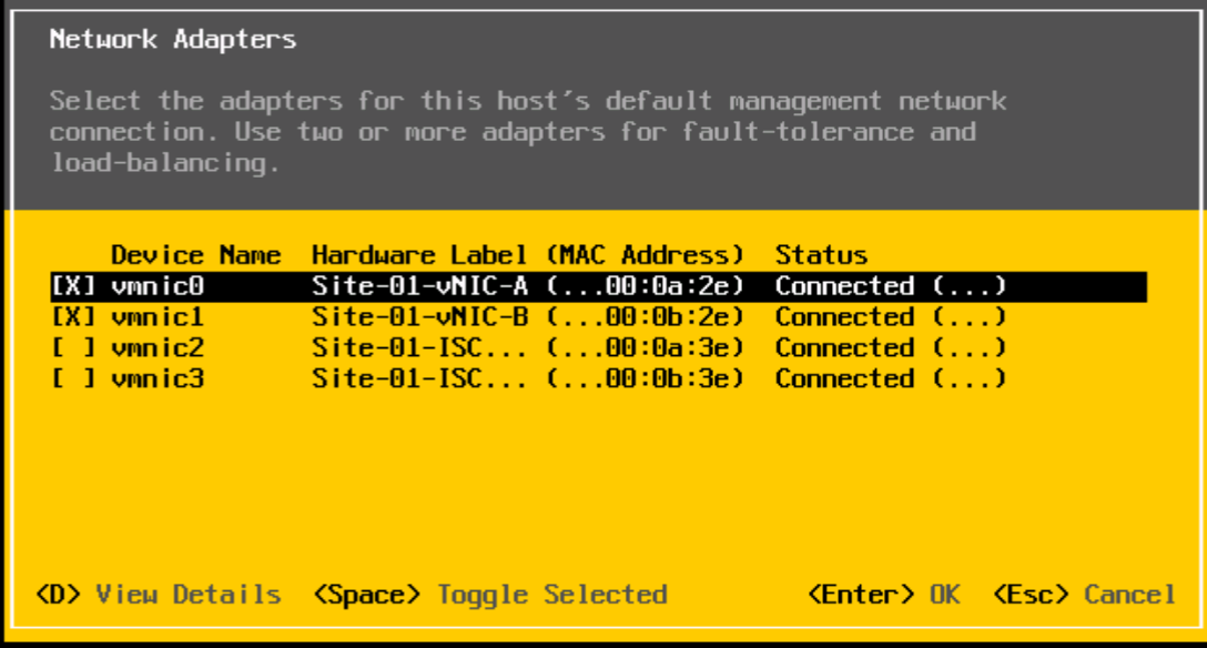
-
Select the VLAN (Optional) option and press Enter.
-
Enter the
<ib-mgmt-vlan-id>and press Enter. -
Select IPv4 Configuration and press Enter.
-
Select the Set Static IPv4 Address and Network Configuration option by using the space bar.
-
Enter the IP address for managing the first ESXi host.
-
Enter the subnet mask for the first ESXi host.
-
Enter the default gateway for the first ESXi host.
-
Press Enter to accept the changes to the IP configuration.
-
Select the DNS Configuration option and press Enter.
Because the IP address is assigned manually, the DNS information must also be entered manually. -
Enter the IP address of the primary DNS server.
-
Optional: Enter the IP address of the secondary DNS server.
-
Enter the FQDN for the first ESXi host.
-
Press Enter to accept the changes to the DNS configuration.
-
Press Esc to exit the Configure Management Network menu.
-
Select Test Management Network to verify that the management network is set up correctly and press Enter.
-
Press Enter to run the test, press Enter again once the test has completed, review environment if there is a failure.
-
Select the Configure Management Network again and press Enter.
-
Select the IPv6 Configuration option and press Enter.
-
Using the spacebar, select Disable IPv6 (restart required) and press Enter.
-
Press Esc to exit the Configure Management Network submenu.
-
Press Y to confirm the changes and reboot the ESXi host.
Reset VMware ESXi host VMkernel port vmk0 MAC address (optional)
ESXi Host VM-Host-Infra-01 and VM-Host-Infra-02
By default, the MAC address of the management VMkernel port vmk0 is the same as the MAC address of the Ethernet port on which it is placed. If the ESXi host’s boot LUN is remapped to a different server with different MAC addresses, a MAC address conflict will occur because vmk0 retains the assigned MAC address unless the ESXi system configuration is reset. To reset the MAC address of vmk0 to a random VMware-assigned MAC address, complete the following steps:
-
From the ESXi console menu main screen, press Ctrl-Alt-F1 to access the VMware console command line interface. In the UCSM KVM, Ctrl-Alt-F1 appears in the list of static macros.
-
Log in as root.
-
Type
esxcfg-vmknic –lto get a detailed listing of interface vmk0. vmk0 should be a part of the Management Network port group. Note the IP address and netmask of vmk0. -
To remove vmk0, enter the following command:
esxcfg-vmknic –d “Management Network”
-
To add vmk0 again with a random MAC address, enter the following command:
esxcfg-vmknic –a –i <vmk0-ip> -n <vmk0-netmask> “Management Network””.
-
Verify that vmk0 has been added again with a random MAC address
esxcfg-vmknic –l
-
Type
exitto log out of the command line interface. -
Press Ctrl-Alt-F2 to return to the ESXi console menu interface.
Log into VMware ESXi hosts with VMware host client
ESXi Host VM-Host-Infra-01
To log in to the VM-Host-Infra-01 ESXi host by using the VMware Host Client, complete the following steps:
-
Open a web browser on the management workstation and navigate to the
VM-Host-Infra-01management IP address. -
Click Open the VMware Host Client.
-
Enter
rootfor the user name. -
Enter the root password.
-
Click Login to connect.
-
Repeat this process to log in to
VM-Host-Infra-02in a separate browser tab or window.
Install VMware drivers for the Cisco Virtual Interface Card (VIC)
Download and extract the offline bundle for the following VMware VIC driver to the Management workstation:
-
nenic Driver version 1.0.25.0
ESXi hosts VM-Host-Infra-01 and VM-Host-Infra-02
To install VMware VIC Drivers on the ESXi host VM-Host-Infra-01 and VM-Host-Infra-02, complete the following steps:
-
From each Host Client, select Storage.
-
Right-click datastore1 and select Browse.
-
In the Datastore browser, click Upload.
-
Navigate to the saved location for the downloaded VIC drivers and select VMW-ESX-6.7.0-nenic-1.0.25.0-offline_bundle-11271332.zip.
-
In the Datastore browser, click Upload.
-
Click Open to upload the file to datastore1.
-
Make sure the file has been uploaded to both ESXi hosts.
-
Place each host into Maintenance mode if it isn’t already.
-
Connect to each ESXi host through ssh from a shell connection or putty terminal.
-
Log in as root with the root password.
-
Run the following commands on each host:
esxcli software vib update -d /vmfs/volumes/datastore1/VMW-ESX-6.7.0-nenic-1.0.25.0-offline_bundle-11271332.zip
reboot
-
Log into the Host Client on each host once reboot is complete and exit Maintenance Mode.
Set up VMkernel ports and virtual switch
ESXi Host VM-Host-Infra-01 and VM-Host-Infra-02
To set up the VMkernel ports and the virtual switches on the ESXi hosts, complete the following steps:
-
From the Host Client, select Networking on the left.
-
In the center pane, select the Virtual switches tab.
-
Select vSwitch0.
-
Select Edit settings.
-
Change the MTU to 9000.
-
Expand NIC teaming.
-
In the Failover order section, select vmnic1 and click Mark active.
-
Verify that vmnic1 now has a status of Active.
-
Click Save.
-
Select Networking on the left.
-
In the center pane, select the Virtual switches tab.
-
Select iScsiBootvSwitch.
-
Select Edit settings.
-
Change the MTU to 9000
-
Click Save.
-
Select the VMkernel NICs tab.
-
Select vmk1 iScsiBootPG.
-
Select Edit settings.
-
Change the MTU to 9000.
-
Expand IPv4 settings and change the IP address to an address outside of the UCS iSCSI-IP-Pool-A.
To avoid IP address conflicts if the Cisco UCS iSCSI IP Pool addresses should get reassigned, it is recommended to use different IP addresses in the same subnet for the iSCSI VMkernel ports. -
Click Save.
-
Select the Virtual switches tab.
-
Select the Add standard virtual switch.
-
Provide a name of
iScsciBootvSwitch-Bfor the vSwitch Name. -
Set the MTU to 9000.
-
Select vmnic3 from the Uplink 1 drop-down menu.
-
Click Add.
-
In the center pane, select the VMkernel NICs tab.
-
Select Add VMkernel NIC
-
Specify a New port group name of iScsiBootPG-B.
-
Select iScsciBootvSwitch-B for Virtual switch.
-
Set the MTU to 9000. Do not enter a VLAN ID.
-
Select Static for the IPv4 settings and expand the option to provide the Address and Subnet Mask within the Configuration.
To avoid IP address conflicts, if the Cisco UCS iSCSI IP Pool addresses should get reassigned, it is recommended to use different IP addresses in the same subnet for the iSCSI VMkernel ports. -
Click Create.
-
On the left, select Networking, then select the Port groups tab.
-
In the center pane, right-click VM Network and select Remove.
-
Click Remove to complete removing the port group.
-
In the center pane, select Add port group.
-
Name the port group Management Network and enter
<ib-mgmt-vlan-id>in the VLAN ID field, and make sure Virtual switch vSwitch0 is selected. -
Click Add to finalize the edits for the IB-MGMT Network.
-
At the top, select the VMkernel NICs tab.
-
Click Add VMkernel NIC.
-
For New port group, enter VMotion.
-
For Virtual switch, select vSwitch0 selected.
-
Enter
<vmotion-vlan-id>for the VLAN ID. -
Change the MTU to 9000.
-
Select Static IPv4 settings and expand IPv4 settings.
-
Enter the ESXi host vMotion IP address and netmask.
-
Select the vMotion stack TCP/IP stack.
-
Select vMotion under Services.
-
Click Create.
-
Click Add VMkernel NIC.
-
For New port group, enter NFS_Share.
-
For Virtual switch, select vSwitch0 selected.
-
Enter
<infra-nfs-vlan-id>for the VLAN ID -
Change the MTU to 9000.
-
Select Static IPv4 settings and expand IPv4 settings.
-
Enter the ESXi host Infrastructure NFS IP address and netmask.
-
Do not select any of the Services.
-
Click Create.
-
Select the Virtual Switches tab, then select vSwitch0. The properties for vSwitch0 VMkernel NICs should be similar to the following example:
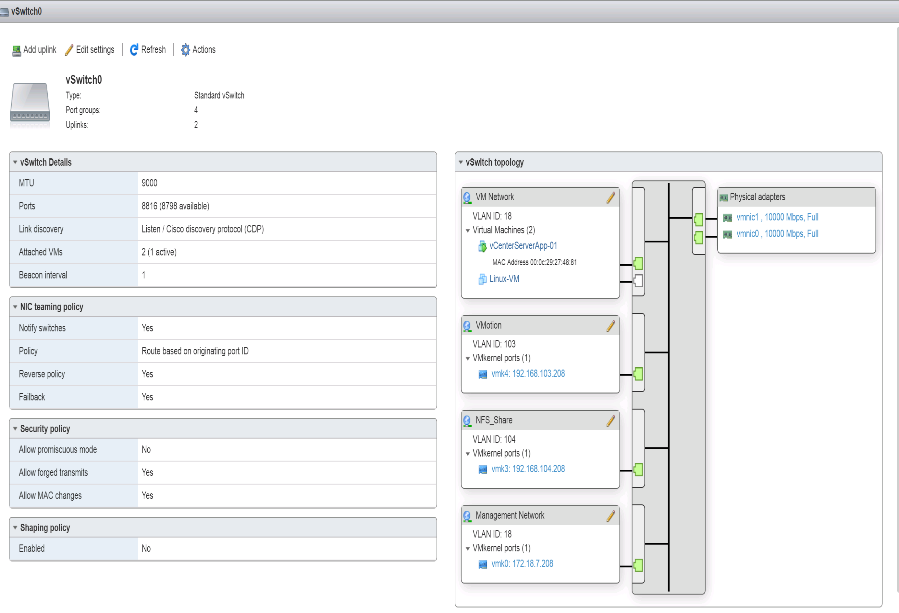
-
Select the VMkernel NICs tab to confirm the configured virtual adapters. The adapters listed should be similar to the following example:
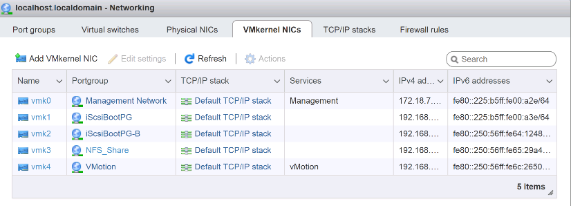
Setup iSCSI multipathing
ESXi Hosts VM-Host-Infra-01 and VM-Host-Infra-02
To set up the iSCSI multipathing on the ESXi host VM-Host-Infra-01 and VM-Host-Infra-02, complete the following steps:
-
From each Host Client, select Storage on the left.
-
In the center pane, click Adapters.
-
Select the iSCSI software adapter and click Configure iSCSI.
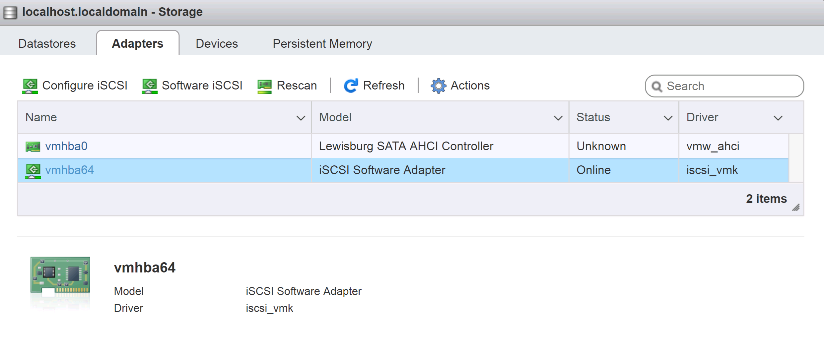
-
Under Dynamic targets, click Add dynamic target.
-
Enter the IP Address of
iSCSI_lif01a. -
Repeat entering these IP addresses:
iscsi_lif01b,iscsi_lif02a, andiscsi_lif02b. -
Click Save Configuration.
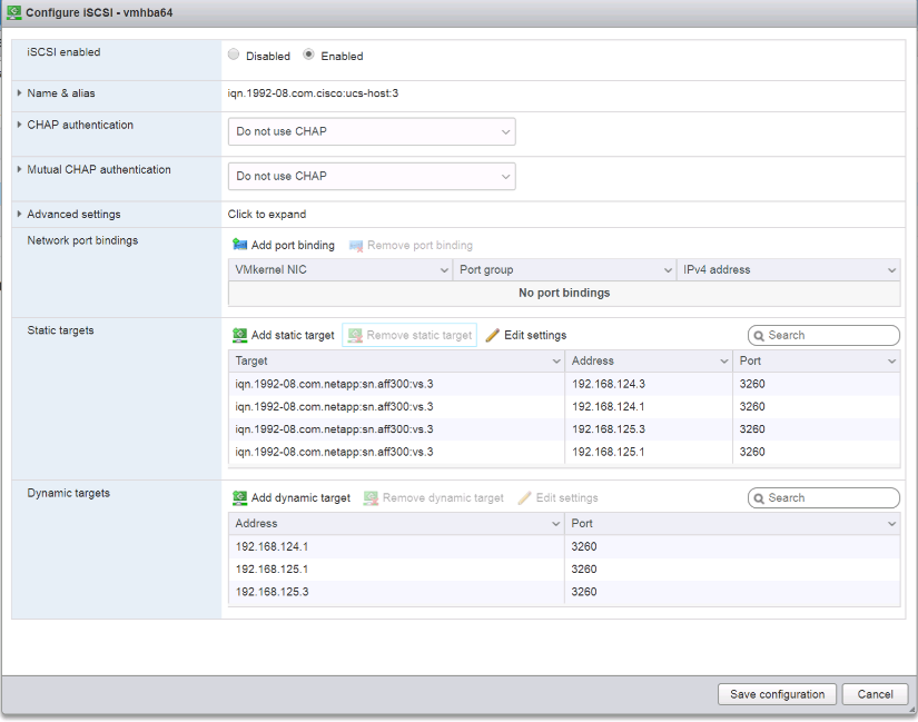
To obtain all of the
iscsi_lifIP addresses, log in to NetApp storage cluster management interface and run thenetwork interface showcommand.
The host automatically rescans the storage adapter and the targets are added to static targets.
Mount required datastores
ESXi Hosts VM-Host-Infra-01 and VM-Host-Infra-02
To mount the required datastores, complete the following steps on each ESXi host:
-
From the Host Client, select Storage on the left.
-
In the center pane, select Datastores.
-
In the center pane, select New Datastore to add a new datastore.
-
In the New datastore dialog box, select Mount NFS datastore and click Next.
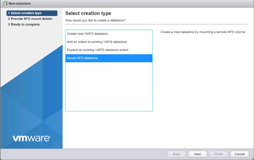
-
On the provide NFS Mount Details page, complete these steps:
-
Enter
infra_datastore_1for the datastore name. -
Enter the IP address for the
nfs_lif01_aLIF for the NFS server. -
Enter
/infra_datastore_1for the NFS share. -
Leave the NFS version set at NFS 3.
-
Click Next.
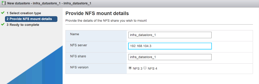
-
-
Click Finish. The datastore should now appear in the datastore list.
-
In the center pane, select New Datastore to add a new datastore.
-
In the New Datastore dialog box, select Mount NFS Datastore and click Next.
-
On the provide NFS Mount Details page, complete these steps:
-
Enter
infra_datastore_2for the datastore name. -
Enter the IP address for the
nfs_lif02_aLIF for the NFS server. -
Enter
/infra_datastore_2for the NFS share. -
Leave the NFS version set at NFS 3.
-
Click Next.
-
-
Click Finish. The datastore should now appear in the datastore list.
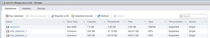
-
Mount both datastores on both ESXi hosts.
Configure NTP on ESXi hosts
ESXi Hosts VM-Host-Infra-01 and VM-Host-Infra-02
To configure NTP on the ESXi hosts, complete the following steps on each host:
-
From the Host Client, select Manage on the left.
-
In the center pane, select the Time & Date tab.
-
Click Edit Settings.
-
Make sure Use Network Time Protocol (enable NTP client) is selected.
-
Use the drop-down menu to select Start and Stop with Host.
-
Enter the two Nexus switch NTP addresses in the NTP servers box separated by a comma.
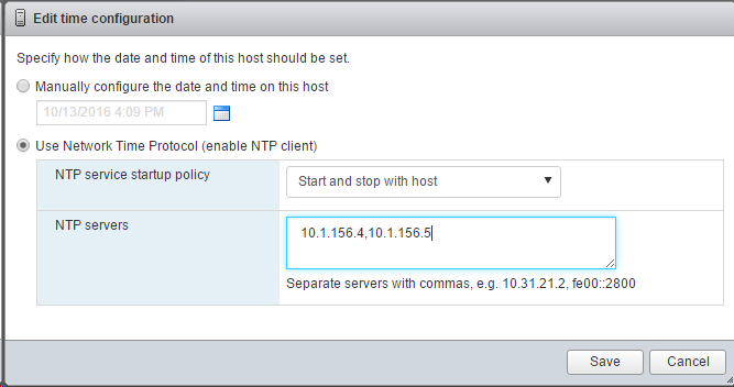
-
Click Save to save the configuration changes.
-
Select Actions > NTP service > Start.
-
Verify that NTP service is now running and the clock is now set to approximately the correct time
The NTP server time might vary slightly from the host time.
Configure ESXi host swap
ESXi Hosts VM-Host-Infra-01 and VM-Host-Infra-02
To configure host swap on the ESXi hosts, follow these steps on each host:
-
Click Manage in the left navigation pane. Select System in the right pane and click Swap.
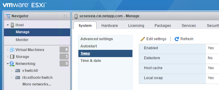
-
Click Edit Settings. Select
infra_swapfrom the Datastore options.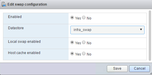
-
Click Save.
Install the NetApp NFS Plug-in 1.1.2 for VMware VAAI
To install the NetApp NFS Plug-in 1. 1.2 for VMware VAAI, complete the following steps.
-
Download the NetApp NFS Plug-in for VMware VAAI:
-
Go to the NetApp software download page.
-
Scroll down and click NetApp NFS Plug-in for VMware VAAI.
-
Select the ESXi platform.
-
Download either the offline bundle (.zip) or online bundle (.vib) of the most recent plug-in.
-
-
The NetApp NFS plug-in for VMware VAAI is pending IMT qualification with ONTAP 9.5 and interoperability details will be posted to the NetApp IMT soon.
-
Install the plug-in on the ESXi host by using the ESX CLI.
-
Reboot the ESXI host.
Install VMware vCenter Server 6.7
This section provides detailed procedures for installing VMware vCenter Server 6.7 in a FlexPod Express configuration.
|
|
FlexPod Express uses the VMware vCenter Server Appliance (VCSA). |
Install VMware vCenter server appliance
To install VCSA, complete the following steps:
-
Download the VCSA. Access the download link by clicking the Get vCenter Server icon when managing the ESXi host.
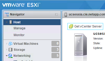
-
Download the VCSA from the VMware site.
Although the Microsoft Windows vCenter Server installable is supported, VMware recommends the VCSA for new deployments. -
Mount the ISO image.
-
Navigate to the
vcsa-ui-installer>win32directory. Double-clickinstaller.exe. -
Click Install.
-
Click Next on the Introduction page.
-
Accept the EULA.
-
Select Embedded Platform Services Controller as the deployment type.
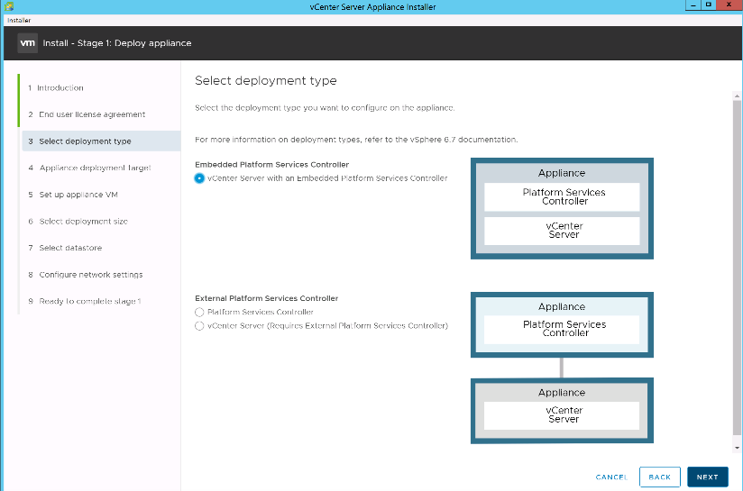
If required, the External Platform Services Controller deployment is also supported as part of the FlexPod Express solution.
-
On the Appliance Deployment Target page, enter the IP address of an ESXi host you have deployed, the root user name, and the root password. Click Next.
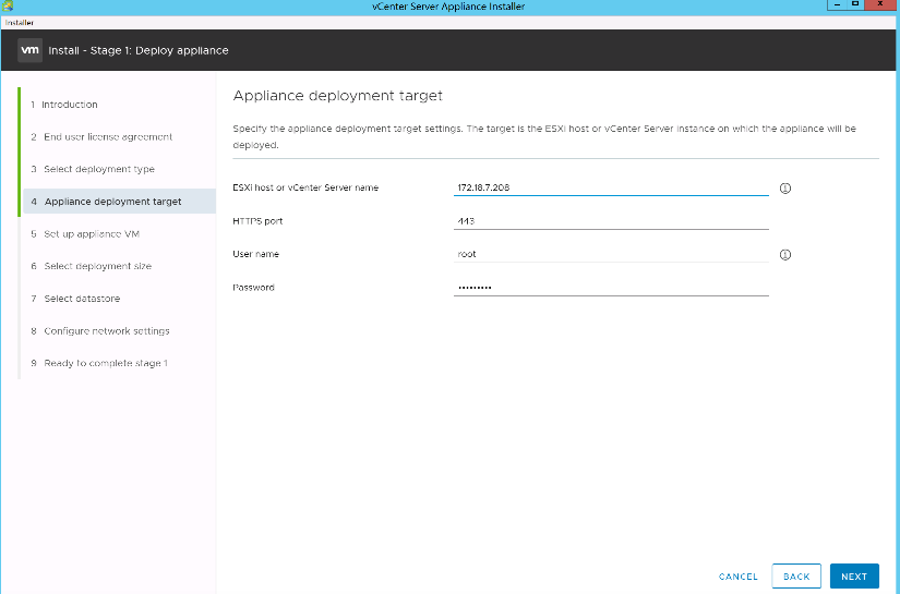
-
Set the appliance VM by entering VCSA as the VM name and the root password you would like to use for the VCSA. Click Next.
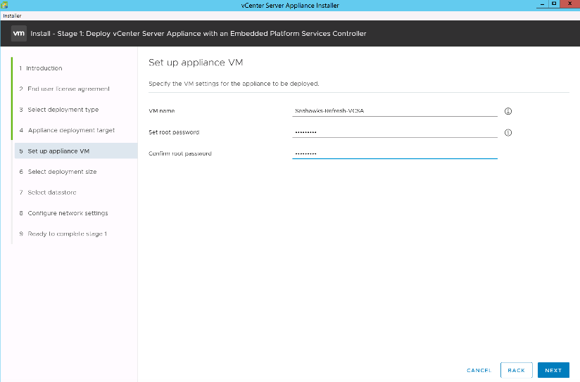
-
Select the deployment size that best fits your environment. Click Next.
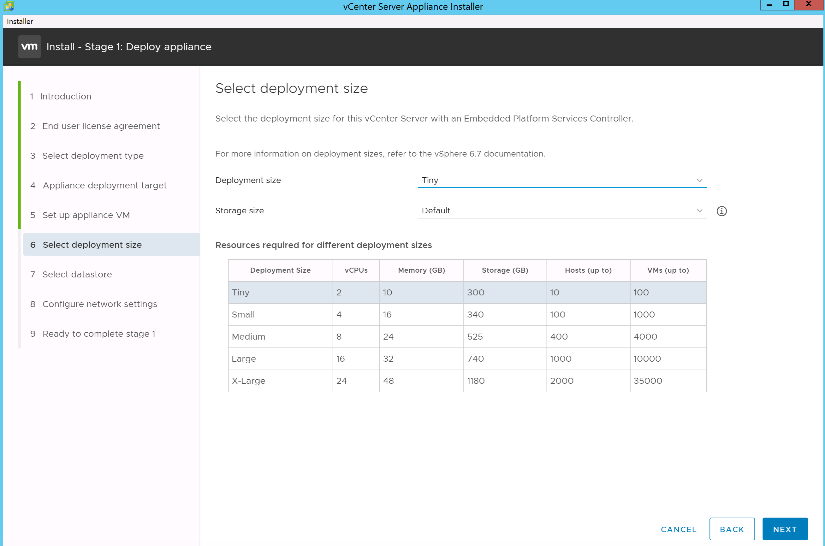
-
Select the
infra_datastore_1datastore. Click Next.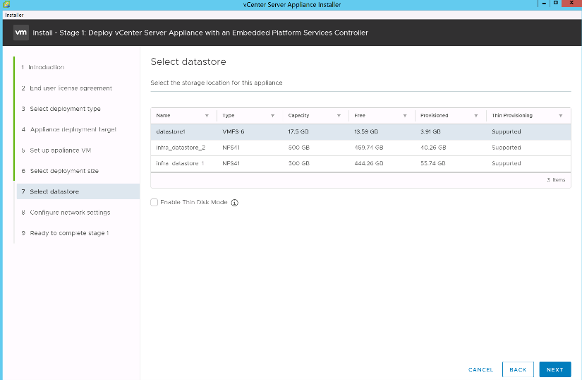
-
Enter the following information on the Configure Network Settings page and click Next.
-
Select MGMT-Network as your network.
-
Enter the FQDN or IP to be used for the VCSA.
-
Enter the IP address to be used.
-
Enter the subnet mask to be used.
-
Enter the default gateway.
-
Enter the DNS server.
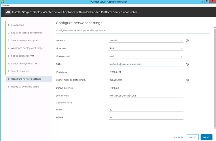
-
-
On the Ready to Complete Stage 1 page, verify that the settings you have entered are correct. Click Finish.
The VCSA installs now. This process takes several minutes.
-
After stage 1 completes, a message appears stating that it has completed. Click Continue to begin stage 2 configuration.
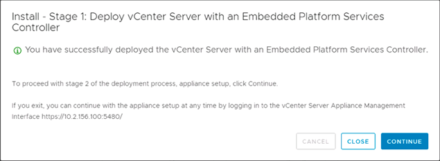
-
On the Stage 2 Introduction page, click Next.
-
Enter
<<var_ntp_id>>for the NTP server address. You can enter multiple NTP IP addresses.If you plan to use vCenter Server high availability, make sure that SSH access is enabled.
-
Configure the SSO domain name, password, and site name. Click Next.
Record these values for your reference, especially if you deviate from the
vsphere.localdomain name. -
Join the VMware Customer Experience Program if desired. Click Next.
-
View the summary of your settings. Click Finish or use the back button to edit settings.
-
A message appears stating that you are not able to pause or stop the installation from completing after it has started. Click OK to continue.
The appliance setup continues. This takes several minutes.
A message appears indicating that the setup was successful.
The links that the installer provides to access vCenter Server are clickable.
Configure VMware vCenter Server 6.7 and vSphere clustering
To configure VMware vCenter Server 6.7 and vSphere clustering, complete the following steps:
-
Navigate to https://<<FQDN or IP of vCenter>>/vsphere-client/.
-
Click Launch vSphere Client.
-
Log in with the user name administrator@vsphere.local and the SSO password you entered during the VCSA setup process.
-
Right-click the vCenter name and select New Datacenter.
-
Enter a name for the data center and click OK.
Create vSphere Cluster.
To create a vSphere cluster, complete the following steps:
-
Right-click the newly created data center and select New Cluster.
-
Enter a name for the cluster.
-
Select and enable DRS and vSphere HA options.
-
Click OK.
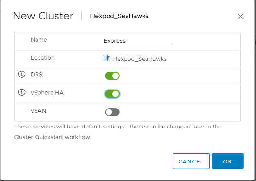
Add ESXi Hosts to Cluster
To add ESXi hosts to the cluster, complete the following steps:
-
Select Add Host in the Actions menu of the cluster.
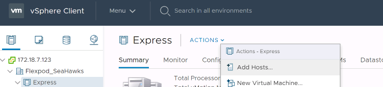
-
To add an ESXi host to the cluster, complete the following steps:
-
Enter the IP or FQDN of the host. Click Next.
-
Enter the root user name and password. Click Next.
-
Click Yes to replace the host’s certificate with a certificate signed by the VMware certificate server.
-
Click Next on the Host Summary page.
-
Click the green + icon to add a license to the vSphere host.
This step can be completed later if desired. -
Click Next to leave lockdown mode disabled.
-
Click Next at the VM location page.
-
Review the Ready to Complete page. Use the back button to make any changes or select Finish.
-
-
Repeat steps 1 and 2 for Cisco UCS host B.
This process must be completed for any additional hosts added to the FlexPod Express configuration.
Configure coredump on ESXi hosts
ESXi Dump Collector Setup for iSCSI-Booted Hosts
ESXi hosts booted with iSCSI using the VMware iSCSI software initiator need to be configured to do core dumps to the ESXi Dump Collector that is part of vCenter. The Dump Collector is not enabled by default on the vCenter Appliance. This procedure should be run at the end of the vCenter deployment section. To setup the ESXi Dump Collector, follow these steps:
-
Log in to the vSphere Web Client as administrator@vsphere.local and select Home.
-
In the center pane, click System Configuration.
-
In the left pane, select Services.
-
Under Services, click VMware vSphere ESXi Dump Collector.
-
In the center pane, click the green start icon to start the service.
-
In the Actions menu, click Edit Startup Type.
-
Select Automatic.
-
Click OK.
-
Connect to each ESXi host using ssh as root.
-
Run the following commands:
esxcli system coredump network set –v vmk0 –j <vcenter-ip>
esxcli system coredump network set –e true
esxcli system coredump network check
The message
Verified the configured netdump server is runningappears after you run the final command.
This process must be completed for any additional hosts added to FlexPod Express.