

Cisco UCS blade server and switch configuration
 Suggest changes
The FlexPod for MEDITECH software is designed with fault tolerance at every level. There is no single point of failure in the system. For optimal performance, Cisco recommends the use of hot spare blade servers.
This document provides high-level guidance on the basic configuration of a FlexPod environment for MEDITECH software. In this section, we present high-level steps with some examples to prepare the Cisco UCS compute platform element of the FlexPod configuration. A prerequisite for this guidance is that the FlexPod configuration is racked, powered, and cabled per the instructions in the FlexPod Datacenter with Fibre Channel Storage using VMware vSphere 6.5 Update 1, NetApp AFF A-series and Cisco UCS Manager 3.2 CVD.
Cisco Nexus switch configuration
A fault- tolerant pair of Cisco Nexus 9300 Series Ethernet switches is deployed for the solution. You should cable these switches as described in the Cabling Diagram section. The Cisco Nexus configuration helps ensure that Ethernet traffic flows are optimized for the MEDITECH application.
-
After you have completed the initial setup and licensing, run the following commands to set global configuration parameters on both switches:
spanning-tree port type network default
spanning-tree port type edge bpduguard default
spanning-tree port type edge bpdufilter default
port-channel load-balance src-dst l4port
ntp server <global-ntp-server-ip> use-vrf management
ntp master 3
ip route 0.0.0.0/0 <ib-mgmt-vlan-gateway>
copy run start
-
Create the VLANs for the solution on each switch using the global configuration mode:
vlan <ib-mgmt-vlan-id>
name IB-MGMT-VLAN
vlan <native-vlan-id>
name Native-VLAN
vlan <vmotion-vlan-id>
name vMotion-VLAN
vlan <vm-traffic-vlan-id>
name VM-Traffic-VLAN
vlan <infra-nfs-vlan-id>
name Infra-NFS-VLAN
exit
copy run start
-
Create the Network Time Protocol (NTP) distribution interface, port channels, port channel parameters, and port descriptions for troubleshooting per FlexPod Datacenter with Fibre Channel Storage using VMware vSphere 6.5 Update 1, NetApp AFF A-series and Cisco UCS Manager 3.2 CVD.
Cisco MDS 9132T configuration
The Cisco MDS 9100 Series FC switches provide redundant 32Gb FC connectivity between the NetApp AFF A200 or AFF A300 controllers and the Cisco UCS compute fabric. You should connect the cables as described in the Cabling Diagram section.
-
From the consoles on each MDS switch, run the following commands to enable the required features for the solution:
configure terminal
feature npiv
feature fport-channel-trunk
-
Configure individual ports, port channels, and descriptions as per the FlexPod Cisco MDS switch configuration section in FlexPod Datacenter with FC Cisco Validated Design.
-
To create the necessary virtual SANs (VSANs) for the solution, complete the following steps while in global configuration mode:
-
For the Fabric-A MDS switch, run the following commands:
vsan database
vsan <vsan-a-id>
vsan <vsan-a-id> name Fabric-A
exit
zone smart-zoning enable vsan <vsan-a-id>
vsan database
vsan <vsan-a-id> interface fc1/1
vsan <vsan-a-id> interface fc1/2
vsan <vsan-a-id> interface port-channel110
vsan <vsan-a-id> interface port-channel112
The port channel numbers in the last two lines of the command were created when the individual ports, port channels, and descriptions were provisioned by using the reference document.
-
For the Fabric-B MDS switch, run the following commands:
vsan database
vsan <vsan-b-id>
vsan <vsan-b-id> name Fabric-B
exit
zone smart-zoning enable vsan <vsan-b-id>
vsan database
vsan <vsan-b-id> interface fc1/1
vsan <vsan-b-id> interface fc1/2
vsan <vsan-b-id> interface port-channel111
vsan <vsan-b-id> interface port-channel113
The port channel numbers in the last two lines of the command were created when the individual ports, port channels, and descriptions were provisioned by using the reference document.
-
-
For each FC switch, create device alias names that make the identification of each device intuitive for ongoing operations by using the details in the reference document.
-
Finally, create the FC zones by using the device alias names that were created in step 4 for each MDS switch as follows:
-
For the Fabric-A MDS switch, run the following commands:
configure terminal
zone name VM-Host-Infra-01-A vsan <vsan-a-id>
member device-alias VM-Host-Infra-01-A init
member device-alias Infra-SVM-fcp_lif01a target
member device-alias Infra-SVM-fcp_lif02a target
exit
zone name VM-Host-Infra-02-A vsan <vsan-a-id>
member device-alias VM-Host-Infra-02-A init
member device-alias Infra-SVM-fcp_lif01a target
member device-alias Infra-SVM-fcp_lif02a target
exit
zoneset name Fabric-A vsan <vsan-a-id>
member VM-Host-Infra-01-A
member VM-Host-Infra-02-A
exit
zoneset activate name Fabric-A vsan <vsan-a-id>
exit
show zoneset active vsan <vsan-a-id>
-
For the Fabric-B MDS switch, run the following commands:
configure terminal
zone name VM-Host-Infra-01-B vsan <vsan-b-id>
member device-alias VM-Host-Infra-01-B init
member device-alias Infra-SVM-fcp_lif01b target
member device-alias Infra-SVM-fcp_lif02b target
exit
zone name VM-Host-Infra-02-B vsan <vsan-b-id>
member device-alias VM-Host-Infra-02-B init
member device-alias Infra-SVM-fcp_lif01b target
member device-alias Infra-SVM-fcp_lif02b target
exit
zoneset name Fabric-B vsan <vsan-b-id>
member VM-Host-Infra-01-B
member VM-Host-Infra-02-B
exit
zoneset activate name Fabric-B vsan <vsan-b-id>
exit
show zoneset active vsan <vsan-b-id>
-
Cisco UCS configuration guidance
Cisco UCS enables you as a MEDITECH customer to leverage your subject- matter experts in network, storage, and compute to create policies and templates that tailor the environment to your specific needs. After they are created, these policies and templates can be combined into service profiles that deliver consistent, repeatable, reliable, and fast deployments of Cisco blade and rack servers.
Cisco UCS provides three methods for managing a Cisco UCS system, called a domain:
-
Cisco UCS Manager HTML5 GUI
-
Cisco UCS CLI
-
Cisco UCS Central for multidomain environments
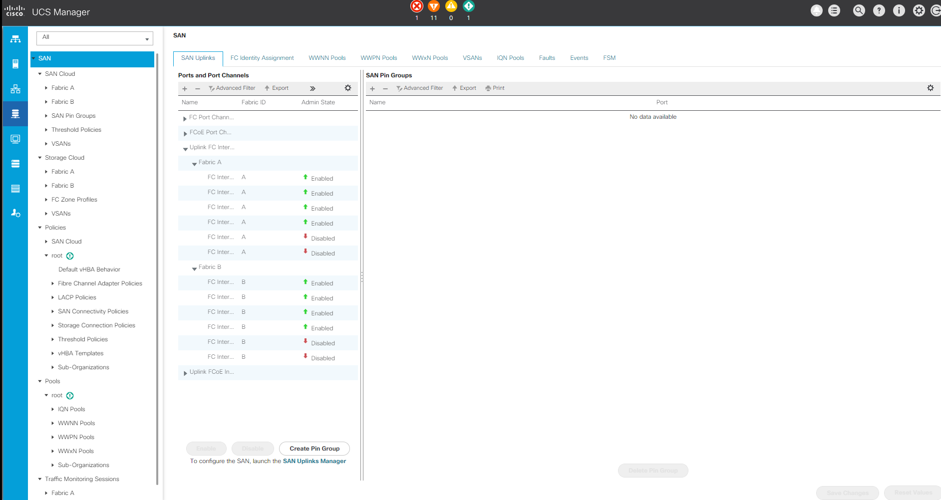
The following figure shows a sample screenshot of the SAN node in Cisco UCS Manager.
In larger deployments, independent Cisco UCS domains can be built for more fault tolerance at the major MEDITECH functional component level.
In highly fault- tolerant designs with two or more data centers, Cisco UCS Central plays a key role in setting global policy and global service profiles for consistency between hosts throughout the enterprise.
To set up the Cisco UCS compute platform, complete the following procedures. Perform these procedures after the Cisco UCS B200 M5 Blade Servers are installed in the Cisco UCS 5108 AC blade chassis. Also, you must compete the cabling requirements as described in the Cabling Diagram section.
-
Upgrade the Cisco UCS Manager firmware to version 3.2(2f) or later.
-
Configure the reporting, Cisco call home features, and NTP settings for the domain.
-
Configure the server and uplink ports on each Fabric Interconnect.
-
Edit the chassis discovery policy.
-
Create the address pools for out- of- band management, universal unique identifiers (UUIDs), MAC address, servers, worldwide node name (WWNN), and worldwide port name (WWPN).
-
Create the Ethernet and FC uplink port channels and VSANs.
-
Create policies for SAN connectivity, network control, server pool qualification, power control, server BIOS, and default maintenance.
-
Create vNIC and vHBA templates.
-
Create vMedia and FC boot policies.
-
Create service profile templates and service profiles for each MEDITECH platform element.
-
Associate the service profiles with the appropriate blade servers.
For the detailed steps to configure each key element of the Cisco UCS service profiles for FlexPod, see the FlexPod Datacenter with Fibre Channel Storage using VMware vSphere 6.5 Update 1, NetApp AFF A-series and Cisco UCS Manager 3.2 CVD document.