NetApp AFF A90 Storage Systems with NVIDIA DGX SuperPOD
 Suggest changes
NVA deployment
The NVIDIA DGX SuperPOD with NetApp AFF A90 storage systems combines the world-class computing performance of NVIDIA DGX systems with NetApp cloud-connected storage systems to enable data-driven workflows for machine learning (ML), artificial intelligence (AI) and high-performance technical computing (HPC). This document describes the configuration and deployment details for integrating AFF A90 storage systems into the DGX SuperPOD architecture.

David Arnette, NetApp
Program summary
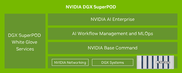
NVIDIA DGX SuperPOD™ offers a turnkey AI data center solution for organizations, seamlessly delivering world-class computing, software tools, expertise, and continuous innovation. DGX SuperPOD delivers everything customers need to deploy AI/ML and HPC workloads with minimal setup time and maximum productivity. Figure 1 shows the high-level components of DGX SuperPOD.
Figure 1) NVIDIA DGX SuperPOD with NetApp AFF A90 storage systems.
DGX SuperPOD provides the following benefits:
-
Proven performance for AI/ML and HPC workloads
-
Integrated hardware and software stack from infrastructure management
and monitoring to pre-built deep learning models and tools. -
Dedicated services from installation and infrastructure management to
scaling workloads and streamlining production AI.
Solution overview
As organizations embrace artificial intelligence (AI) and machine learning (ML) initiatives, the demand for robust, scalable, and efficient infrastructure solutions has never been greater. At the heart of these initiatives lies the challenge of managing and training increasingly complex AI models while ensuring data security, accessibility, and resource optimization.
This solution offers the following key benefits:
-
Scalability
-
Data Management and access
-
Security
Solution technology
NVIDIA DGX SuperPOD includes the servers, networking and storage
necessary to deliver proven performance for demanding AI workloads. NVIDIA DGX™ H200 and B200 systems provide world-class computing power, and NVIDIA Quantum InfiniBand and Spectrum™ Ethernet network switches provide ultra-low latency and industry leading network performance. With the addition of the industry-leading data management and performance capabilities of NetApp ONTAP storage, customers can deliver on AI/ML initiatives faster and with less data migration and administrative overhead. For more information on the specific components in this solution please refer to the
NVA-1175 DESIGN GUIDE and NVIDIA DGX SuperPOD Reference architecture documentation.
Use case summary
NVIDIA DGX SuperPOD is designed to meet the performance and scale requirements of the most demanding workloads.
This solution applies to the following use cases:
-
Machine learning at massive scale using traditional analytics tools.
-
Artificial intelligence model training for Large Language Models,
computer vision/image classification, fraud detection and countless
other use cases. -
High performance computing such as seismic analysis, computational
fluid dynamics and large-scale visualization.
Technology requirements
DGX SuperPOD is based on the concept of a Scalable Unit (SU) that includes all of the components necessary to deliver the required connectivity and performance and eliminate any bottlenecks in the infrastructure. Customers can start with a single or multiple SUs and add additional SUs as needed to meet their requirements. For more information please refer to the NVIDIA DGX SuperPOD reference architecture. This document describes the storage components and configuration for a single SU.
Hardware requirements
Table 1 lists the hardware components that are required to implement the storage components for 1SU. Please refer to Appendix A for specific parts and quantities for 1-4 Scalable Units.
Table 1) Hardware requirements.
| Hardware | Quantity |
|---|---|
NetApp AFF A90 storage system |
4 |
NetApp storage cluster interconnect switch |
2 |
NVIDIA 800GB → 4x 200Gb splitter cables |
12 |
Software requirements
Table 2 lists the minimum software components and versions that are required to integrate the AFF A90 storage system with DGX SuperPOD. DGX SuperPOD also involves other software components that are not listed here. Please refer to the
DGX SuperPOD release notes for complete details.
Table 2) Software requirements.
| Software | Version |
|---|---|
NetApp ONTAP |
9.16.1 or above |
NVIDIA BaseCommand Manager |
10.24.11 or above |
NVIDIA DGX OS |
6.3.1 or above |
NVIDIA OFED driver |
MLNX_OFED_LINUX-23.10.3.2.0 LTS or above |
NVIDIA Cumulus OS |
5.10 or above |
Deployment procedures
Integrating NetApp ONTAP storage with DGX SuperPOD involves the
following tasks:
-
Network configuration for NetApp AFF A90 storage systems with RoCE
-
Storage system installation and configuration
-
DGX client configuration with NVIDIA Base Command™ Manager
Storage system installation and configuration
Site preparation and basic installation
Site preparation and basic installation of the AFF A90 storage cluster will be performed by NetApp Professional Services for all DGX SuperPOD deployments as part of the standard deployment service. NetApp PS will confirm that site conditions are appropriate for installation and install the hardware in the designated racks. They will also connect the OOB network connections and complete basic cluster setup using network information provided by the customer. Appendix A – Bill of Materials and Rack Elevations includes standard rack elevations for reference. For more information on A90 installation please refer to the AFF A90 hardware installation documentation.
Once the standard deployment is complete, NetApp PS will complete the Advanced configuration of the storage solution using the procedures below, including integration with Base Command Manager for client connectivity and tuning.
Cabling the storage system to the DGX SuperPOD storage fabric
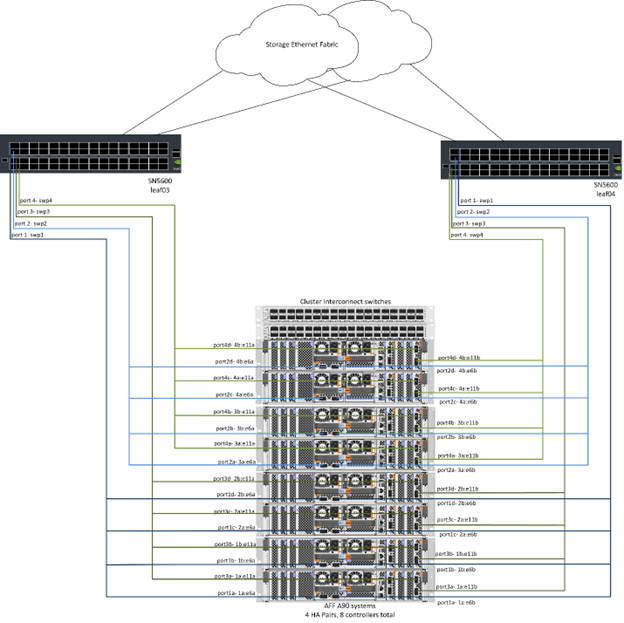
The AFF A90 storage system is connected to the storage fabric leaf switches using four 200Gb Ethernet ports per controller, with two connections to each switch. The 800Gb switch ports on the NVIDIA Spectrum SN5600 switches are broken into 4x 200Gb ports using the appropriate DAC or optical splitter configurations listed in Appendix A. The individual ports from each switch port are distributed across the storage controller to eliminate single points of failure. Figure 2 below shows the cabling for the storage fabric connections:
Figure 2) Storage network cabling.
Cabling the storage system to the DGX SuperPOD in-band network
NetApp ONTAP includes industry-leading multi-tenancy capabilities that enable it to operate both as the high-performance storage system in the DGX SuperPOD architecture, and also to support home directories, group
file shares and Base Command Manager cluster artifacts. For use on the in-band network, each AFF A90 controller is connected to the in-band network switches with one 200Gb Ethernet connection per controller, and the ports are configured in an LACP MLAG configuration. Figure 3 below shows the cabling of the storage system to the in-band and OOB networks.
Figure 3) In-band and OOB network cabling.

Configure ONTAP for DGX SuperPOD
This solution leverages multiple Storage Virtual Machines (SVM) to host volumes for both high-performance storage access as well as user home directories and other cluster artifacts on a management SVM. Each SVM is configured with network interfaces on the storage or in-band networks, and FlexGroup volumes for data storage. To ensure performance for the Data SVM a storage QoS policy is implemented. For more information on FlexGroups, Storage Virtual Machines and ONTAP QoS capabilities please
refer to the ONTAP documentation.
Configure Base Storage
Configure a single aggregate on each controller
aggr create -node <node> -aggregate <node>_data01 -diskcount <47> -maxraidsize 24Repeat the steps above for each node in the cluster.
Configure ifgrps on each controller for in-band network
net port ifgrp create -node <node> -ifgrp a1a -mode multimode
-distr-function port

net port ifgrp add-port -node <node> -ifgrp a1a -ports
<node>:e2a,<node>:e2b
Repeat the steps above for each node in the cluster.
Configure physical ports for RoCE
Enabling NFS over RDMA requires configuration to ensure network traffic is tagged appropriately at both the client and server and is then handled appropriately by the network using RDMA over Converged Ethernet (RoCE). This includes configuring Priority Flow Control (PFC) and configuring the PFC CoS queue to be used. NetApp ONTAP also automatically configures DSCP code 26 to align with the network QoS configuration when the commands below are executed.
network port modify -node * -port e6* -flowcontrol-admin pfc
-pfc-queues-admin 3

network port modify -node * -port e11* -flowcontrol-admin pfc
-pfc-queues-admin 3
Create broadcast domains
broadcast-domain create -broadcast-domain in-band -mtu 9000 -ports
ntapa90_spod-01:a1a,ntapa90_spod-02:a1a,ntapa90_spod-03:a1a,ntapa90_spod-04:a1a,ntapa90_spod-05:a1a,
ntapa90_spod-06:a1a,ntapa90_spod-07:a1a,ntapa90_spod-08:a1a

broadcast-domain create -broadcast-domain vlan401 -mtu 9000 -ports
ntapa90_spod-01:e6a,ntapa90_spod-01:e6b,ntapa90_spod-02:e6a,ntapa90_spod-02:e6b,ntapa90_spod-03:e6a,ntapa90_spod-03:e6b,ntapa90_spod-04:e6a,ntapa90_spod-04:e6b,ntapa90_spod-05:e6a,ntapa90_spod-05:e6b,ntapa90_spod-06:e6a,ntapa90_spod-06:e6b,ntapa90_spod-07:e6a,ntapa90_spod-07:e6b,ntapa90_spod-08:e6a,ntapa90_spod-08:e6b

broadcast-domain create -broadcast-domain vlan402 -mtu 9000 -ports
ntapa90_spod-01:e11a,ntapa90_spod-01:e11b,ntapa90_spod-02:e11a,ntapa90_spod-02:e11b,ntapa90_spod-03:e11a,ntapa90_spod-03:e11b,ntapa90_spod-04:e11a,ntapa90_spod-04:e11b,ntapa90_spod-05:e11a,ntapa90_spod-05:e11b,ntapa90_spod-06:e11a,ntapa90_spod-06:e11b,ntapa90_spod-07:e11a,ntapa90_spod-07:e11b,ntapa90_spod-08:e11a,ntapa90_spod-08:e11b
Create Management SVM
Create and configure Management SVM
vserver create -vserver spod_mgmt

vserver modify -vserver spod_mgmt -aggr-list
ntapa90_spod-01_data01,ntapa90_spod-02_data01,
ntapa90_spod-03_data01,ntapa90_spod-04_data01,
ntapa90_spod-05_data01,ntapa90_spod-06_data01,
ntapa90_spod-07_data01,ntapa90_spod-08_data01
Configure NFS service on Management SVM
nfs create -vserver spod_mgmt -v3 enabled -v4.1 enabled -v4.1-pnfs
enabled -tcp-max-xfer-size 262144 -v4.1-trunking enabled

set advanced

nfs modify -vserver spod_mgmt -v3-64bit-identifiers enabled
-v4.x-session-num-slots 1024
Create IP subnets for In-Band network interfaces
network subnet create -subnet-name inband -broadcast-domain in-band
-subnet xxx.xxx.xxx.0/24 -gateway xxx.xxx.xxx.x -ip-ranges
xxx.xxx.xxx.xx-xxx.xxx.xxx.xxx
Note: IP Subnet information to be provided by customer at time of deployment for integration into existing customer networks.
Create network interfaces on each node for In-Band SVM
net int create -vserver spod_mgmt -lif inband_lif1 -home-node
ntapa90_spod-01 -home-port a1a -subnet_name inband
Repeat the steps above for each node in the cluster.
Create FlexGroup volumes for Management SVM
vol create -vserver spod_mgmt -volume home -size 10T -auto-provision-as
flexgroup -junction-path /home

vol create -vserver spod_mgmt -volume cm -size 10T -auto-provision-as
flexgroup -junction-path /cm
Create export policy for Management SVM
export-policy rule create -vserver spod_mgmt -policy default
-client-match XXX.XXX.XXX.XXX -rorule sys -rwrule sys -superuser sys
Note: IP Subnet information to be provided by customer at time of deployment for integration into existing customer networks.
Create Data SVM
Create and configure Data SVM
vserver create -vserver spod_data
vserver modify -vserver spod_data -aggr-list
ntapa90_spod-01_data01,ntapa90_spod-02_data01,
ntapa90_spod-03_data01,ntapa90_spod-04_data01,
ntapa90_spod-05_data01,ntapa90_spod-06_data01,
ntapa90_spod-07_data01,ntapa90_spod-08_data01
Configure NFS service on Data SVM with RDMA enabled
nfs create -vserver spod_data -v3 enabled -v4.1 enabled -v4.1-pnfs
enabled -tcp-max-xfer-size 262144 -v4.1-trunking enabled -rdma enabled

set advanced

nfs modify -vserver spod_data -v3-64bit-identifiers enabled
-v4.x-session-num-slots 1024
Create IP subnets for Data SVM network interfaces
network subnet create -subnet-name vlan401 -broadcast-domain vlan401
-subnet 100.127.124.0/24 -ip-ranges 100.127.124.4-100.127.124.254

network subnet create -subnet-name vlan402 -broadcast-domain vlan402
-subnet 100.127.252.0/24 -ip-ranges 100.127.252.4-100.127.252.254
Create network interfaces on each node for Data SVM
net int create -vserver spod_data -lif data_lif1 -home-node
ntapa90_spod-01 -home-port e6a -subnet_name vlan401 -failover-policy
sfo-partner-only

net int create -vserver spod_data -lif data_lif2 -home-node
ntapa90_spod-01 -home-port e6b -subnet_name vlan401

net int create -vserver spod_data -lif data_lif3 -home-node
ntapa90_spod-01 -home-port e11a -subnet_name vlan402

net int create -vserver spod_data -lif data_lif4 -home-node
ntapa90_spod-01 -home-port e11b -subnet_name vlan402
Repeat the steps above for each node in the cluster.
Configure Data SVM network interfaces for RDMA
net int modify -vserver spod_data -lif * -rdma-protocols roceCreate export policy on data SVM
export-policy rule create -vserver spod_data -policy default
-client-match 100.127.0.0/16 -rorule sys -rwrule sys -superuser sys
Create static routes on data SVM
route add -vserver spod_data -destination 100.127.0.0/17 -gateway
100.127.124.1 -metric 20

route add -vserver spod_data -destination 100.127.0.0/17 -gateway
100.127.252.1 -metric 30

route add -vserver spod_data -destination 100.127.128.0/17 -gateway
100.127.252.1 -metric 20

route add -vserver spod_data -destination 100.127.128.0/17 -gateway
100.127.124.1 -metric 30
Create FlexGroup volume with GDD for Data SVM
Granular Data Distribution (GDD) enables large data files to be
distributed across multiple FlexGroup constituent volumes and
controllers to enable maximum performance for single-file workloads. NetApp recommends enabling GDD on data volumes for all DGX SuperPOD deployments.
set adv

vol create -vserver spod-data -volume spod_data -size 100T -aggr-list
ntapa90_spod-01_data01,ntapa90_spod-02_data01,
ntapa90_spod-03_data01,ntapa90_spod-04_data01,
ntapa90_spod-05_data01,ntapa90_spod-06_data01,
ntapa90_spod-07_data01,ntapa90_spod-08_data01 -aggr-multiplier 16
-granular-data advanced -junction-path /spod_data
Disable storage efficiency for primary data volume
volume efficiency off -vserver spod_data -volume spod_data
Create QoS minimum policy for data SVM
qos policy-group create -policy-group spod_qos -vserver spod_data
-min-throughput 62GB/s -is-shared true
Apply QoS policy for data SVM
Volume modify -vserver spod_data -volume spod_data -qos-policy-group
spod_qos
DGX server configuration with NVIDIA Base Command Manager
To prepare the DGX clients to use the AFF A90 storage system, complete the following tasks. This process assumes that network interfaces and static routes for the storage fabric have already been configured on the DGX system nodes. The following tasks will be completed by NetApp Professional Services as part of the advanced configuration process.
Configure DGX server image with required kernel parameters and other settings
NetApp ONTAP uses industry-standard NFS protocols and does not require any additional software to be installed on the DGX systems. In order to deliver optimum performance from the client systems several modifications to the DGX system image are required. Both of the following steps are performed after entering the BCM image chroot mode by using the command below:
cm-chroot-sw-img /cm/images/<image>Configure system virtual memory settings in /etc/sysctl.conf
Default Linux system configuration provides virtual memory settings that may not necessarily deliver optimal performance. In the case of DGX B200 systems with 2TB RAM, the default settings allow for 40GB of buffer space which creates inconsistent I/O patterns and allows the client to overload the storage system when flushing the buffer. The settings below
limit client buffer space to 5GB and force flushing more often to create a consistent I/O stream that does not overload the storage system.
After entering the image chroot mode, edit the
/etc/sysctl.s/90-cm-sysctl.conf file and add the following lines:
vm.dirty_ratio=0 #controls max host RAM used for buffering as a
percentage of total RAM, when this limit is reached all applications
must flush buffers to continue

vm.dirty_background_ratio=0 #controls low-watermark threshold to start
background flushing as a percentage of total RAM

vm.dirty_bytes=5368709120 #controls max host RAM used for buffering as
an absolute value (note _ratio above only accepts integers and the value
we need is <1% of total RAM (2TB))

vm.dirty_background_bytes=2147483648 #controls low-watermark threshold
to start background flushing as an absolute value

vm.dirty_expire_centisecs = 300 #controls how long data remains in
buffer pages before being marked dirty

vm.dirty_writeback_centisecs = 100 #controls how frequently the flushing
process wakes up to flush dirty buffers
Save and close the /etc/sysctl.conf file.
Configure other system settings with a script that executes after reboot
Some settings require the OS to be fully online to execute and are not persistent after a reboot. To perform these settings in a Base Command Manager environment, create a file /root/ntap_dgx_config.sh and enter the following lines:
#!/bin/bash

##The commands below are platform-specific based.

##For H100/H200 systems use the following variables

## NIC1_ethname= enp170s0f0np0

## NIC1_pciname=aa:00.0

## NCI1_mlxname=mlx5_7

## NIC1_ethname= enp41s0f0np0

## NIC1_pciname=29:00.0

## NCI1_mlxname=mlx5_1

##For B200 systems use the following variables

NIC1_ethname=enp170s0f0np0

NIC1_pciname=aa:00.0

NCI1_mlxname=mlx5_11

NIC2_ethname=enp41s0f0np0

NIC2_pciname=29:00.0

NCI2_mlxname=mlx5_5

mstconfig -y -d $\{NIC1_pciname} set ADVANCED_PCI_SETTINGS=1
NUM_OF_VFS=0

mstconfig -y -d $\{NIC2_pciname} set ADVANCED_PCI_SETTINGS=1
NUM_OF_VFS=0

setpci -s $\{NIC1_pciname} 68.W=5957

setpci -s $\{NIC2_pciname} 68.W=5957

ethtool -G $\{NIC1_ethname} rx 8192 tx 8192

ethtool -G $\{NIC2_ethname} rx 8192 tx 8192

mlnx_qos -i $\{NIC1_ethname} --pfc 0,0,0,1,0,0,0,0 --trust=dscp

mlnx_qos -i $\{NIC2_ethname} --pfc 0,0,0,1,0,0,0,0 --trust=dscp

echo 106 > /sys/class/infiniband/$\{NIC1_mlxname}/tc/1/traffic_class

echo 106 > /sys/class/infiniband/$\{NIC2_mlxname}/tc/1/traffic_class
Save and close the file. Change the permissions on the file so it is executable:
chmod 755 /root/ntap_dgx_config.shCreate a cron job that is executed by root at boot by editing the following line:
@reboot /root/ntap_dgx_config.shSee the example crontab file below:
# Edit this file to introduce tasks to be run by cron.

#

# Each task to run has to be defined through a single line

# indicating with different fields when the task will be run

# and what command to run for the task

#

# To define the time you can provide concrete values for

# minute (m), hour (h), day of month (dom), month (mon),

# and day of week (dow) or use '*' in these fields (for 'any').

#

# Notice that tasks will be started based on the cron's system

# daemon's notion of time and timezones.

#

# Output of the crontab jobs (including errors) is sent through

# email to the user the crontab file belongs to (unless redirected).

#

# For example, you can run a backup of all your user accounts

# at 5 a.m every week with:

# 0 5 * * 1 tar -zcf /var/backups/home.tgz /home/

#

# For more information see the manual pages of crontab(5) and cron(8)

#

# m h dom mon dow command

@reboot /home/ntap_dgx_config.sh
Exit the BCM image chroot mode by entering exit or Ctrl-D.
Configure BaseCommand Manager DGX category for client mount points
To configure the DGX clients mount the AFF A90 storage system, the BCM client category used by the DGX systems should be modified to include the relevant information and options. The steps below describe how to configure the NFS mount point.
cmsh

category ; use category <category>; fsmounts

add superpod

set device 100.127.124.4:/superpod

set mountpoint /mnt/superpod

set filesystem nfs

set mountoptions
vers=4.1,proto=rdma,max_connect=16,write=eager,rsize=262144,wsize=262144

commit
Conclusion
The NVIDIA DGX SuperPOD with NetApp AFF A90 storage systems represents a significant advancement in AI infrastructure solutions. By addressing key challenges around security, data management, resource utilization, and scalability, it enables organizations to accelerate their AI initiatives while maintaining operational efficiency, data protection, and collaboration. The solution's integrated approach eliminates common bottlenecks in AI development pipelines, enabling data scientists and engineers to focus on innovation rather than infrastructure management.
Where to find additional information
To learn more about the information that is described in this document, review the following documents and/or websites:
-
NVA-1175
NVIDIA DGX SuperPOD with NetApp AFF A90 Storage Systems Design Guide -
What is pNFS
(older doc with great pNFS info)
Appendix A: Bill of Materials and Rack Elevations
Bill of Materials
Table 3 shows the part number and quantities of the NetApp components required to deploy the storage for one, two, three and four scalable units.
Table 3) NetApp BOM for 1, 2, 3, and 4 SU.
| Part # | Item | Quantity for 1SU | Quantity for 2SU | Quantity for 3SU | Quantity for 4SU |
|---|---|---|---|---|---|
AFF-A90A-100-C |
AFF A90 Storage system |
4 |
8 |
12 |
16 |
X4025A-2-A-C |
2x7.6TB drive pack |
48 |
96 |
144 |
192 |
X50131A-C |
IO Module, 2PT,100/200/400GbE |
24 |
48 |
96 |
128 |
X50130A-C |
IO Module, 2PT, 100GbE |
16 |
32 |
48 |
64 |
X-02659-00 |
Kit, 4-Post, Square or Round-Hole, 24"-32" Rail |
4 |
8 |
12 |
16 |
X1558A-R6 |
Pwr Cord, In-Cabinet,48-In, |
20 |
40 |
60 |
80 |
X190200-CS |
Cluster Switch, N9336C 36Pt PTSX10/25/40/100G |
2 |
4 |
6 |
8 |
X66211A-2 |
Cable, 100GbE ,QSFP28-QSFP28, Cu, 2m |
16 |
32 |
48 |
64 |
X66211A-05 |
Cable, 100GbE, QSFP28-QSFP28, Cu, 0.5m |
4 |
8 |
12 |
16 |
X6561-R6 |
Cable, Ethernet, CAT6, RJ45, 5m |
18 |
34 |
50 |
66 |
Table 4 shows the part number and quantity of NVIDIA cables required to
connect the AFF A90 storage systems to the SN5600 switches in the
high-performance storage and in-band networks.
Table 4) NVIDIA cables required for connecting AFF A90 storage systems
to the SN5600 switches in the high-performance storage and in-band
networks.
| Part # | Item | Quantity for 1SU | Quantity for 2SU | Quantity for 3SU | Quantity for 4SU |
|---|---|---|---|---|---|
MCP7Y40-N003 |
DAC 3m 26ga 2x400G to 4x200G OSFP to 4xQSFP112 |
12 |
24 |
36 |
48 |
OR |
|||||
MMS4X00-NS |
Twin port OSFP 2x400G 2xSR4 Multimode Transceiver Dual |
12 |
24 |
36 |
48 |
MFP7E20-N0XX |
Multimode Fibers Splitters 400G→ 2x200G XX = 03, 05, 07, |
24 |
48 |
96 |
128 |
MMA1Z00-NS400 |
Single Port 400G SR4 Multimode QSFP112Transceiver Single |
48 |
96 |
144 |
192 |
Rack Elevations
Figures 4-6 show example rack elevations for 1-4 SU.
Figure 4) Rack elevations for 1 SU and 2 SU.
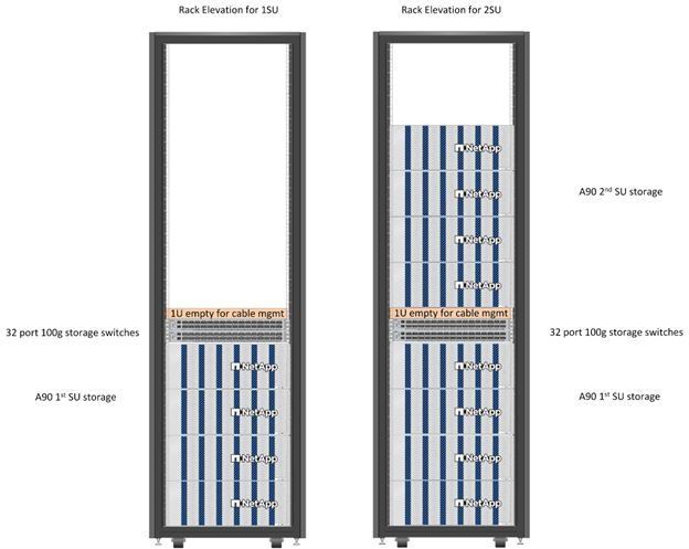
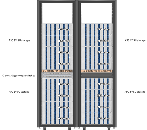
Figure 5) Rack elevations for 3 SU.
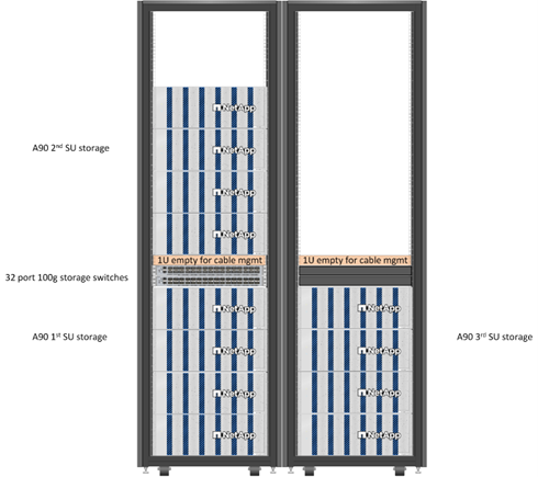
Figure 6) Rack elevations for 4 SU.