


Lustre with NetApp E-Series Storage - Hardware Components
 Suggest changes

 PDFs
PDFs
Use these hardware requirements for servers, NetApp E-Series arrays, storage layout, and networking when you size and order Lustre with NetApp E-Series Storage. For software components, see Software components.
Server requirements
The solution uses a bring-your-own-server (BYOS) model. Each building block requires two OSS/MDS server nodes that meet or exceed the following specifications.
Node specifications
The following table lists the minimum server requirements per OSS/MDS node.
| Component | Requirement |
|---|---|
Quantity |
2 nodes per building block |
CPU |
AMD EPYC or Intel Xeon, 32 cores or higher |
Memory |
256 GB DDR5 (minimum) |
Network HCAs |
6 dual-port 200Gb HCAs (see HCA connectivity) |
PCIe slots |
2× PCIe Gen5 x16 and 4× PCIe Gen5 x8 (see PCIe slot requirements) |
Boot drives |
2× drives in RAID 1 (software or hardware RAID recommended) |
NetApp validated the solution using Lenovo ThinkSystem SR665 V3 servers. Equivalent servers from other vendors are supported when they meet these requirements.
HCA connectivity
The following table lists HCA, LNet frontend port, and NVMe-oF path requirements per OSS/MDS server node.
| HCAs per node | LNet ports per Lustre node | NVMe-oF paths per Lustre node | Example HCA |
|---|---|---|---|
6 (12 ports) |
4 |
8 total (4 to each array) |
MCX755106AS-HEAT (Dual port 200Gb PCIe gen5 card) |
NetApp recommends six HCAs per node to maximize the bandwidth of the EF80 storage arrays.
PCIe slot requirements
Each OSS/MDS server node in an EF80 building block holds six dual-port HCAs: two for LNet and four for NVMe-oF. Slot width determines the bandwidth available to each HCA, so confirm the electrical width of every slot and riser rather than the width of the card alone. A Gen5 x16 card installed in a Gen5 x8 slot runs at x8.
-
LNet HCAs: Install in PCIe Gen5 x16 slots to reach full frontend throughput.
-
NVMe-oF HCAs: Install in PCIe Gen5 x8 or PCIe Gen5 x16 slots.
-
NUMA balance: Divide the HCAs evenly between the two NUMA zones so that each zone hosts two LNet interfaces and four NVMe-oF interfaces.
The following table lists the minimum slots for each OSS/MDS server node in an EF80 building block.
| Traffic type | HCAs per node | Minimum slot width | Slots per NUMA zone |
|---|---|---|---|
LNet |
2 |
PCIe Gen5 x16 |
1 |
NVMe-oF |
4 |
PCIe Gen5 x8 |
2 |
Optionally, you can split the ports on a dual-port HCA so that one port carries LNet traffic and the other carries NVMe-oF traffic. Install all four of these HCAs in PCIe Gen5 x16 slots so that every LNet port reaches full throughput, then add two more HCAs in Gen5 x8 or Gen5 x16 slots for the remaining NVMe-oF ports.
Example riser configurations for Lenovo ThinkSystem SR665 V3
Both of the following riser combinations meet the slot requirements for an EF80 building block.
Minimum slot widths
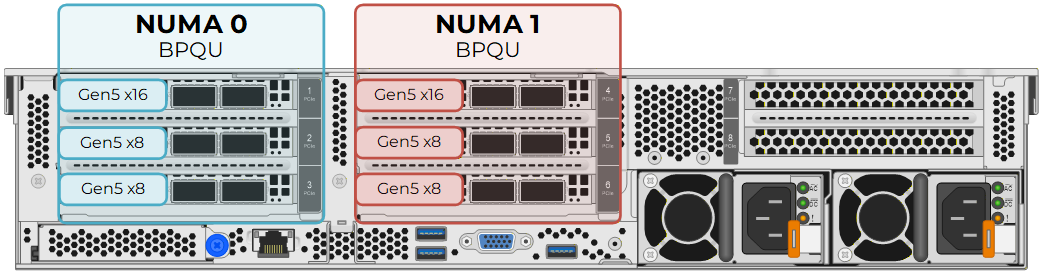
Install a BPQU riser in riser positions 1 and 2. Each BPQU riser provides one PCIe Gen5 x16 slot and two PCIe Gen5 x8 slots. Together, the risers provide two Gen5 x16 slots for LNet and four Gen5 x8 slots for NVMe-oF, evenly divided between the NUMA zones.
All Gen5 x16 slots
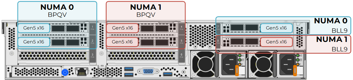
Install a BPQV riser in riser positions 1 and 2, and a BLL9 riser in riser position 3. Each BPQV riser provides two PCIe Gen5 x16 slots. The BLL9 riser provides slot 7 on NUMA zone 0 and slot 8 on NUMA zone 1, both PCIe Gen5 x16. This combination provides six Gen5 x16 slots, three per NUMA zone, and supports splitting LNet and NVMe-oF traffic across the ports of the same HCA.
EF80 standard building block
The EF80 is the validated standard platform for this solution release.
Array specifications
The following table lists EF80 array specifications for a building block (two arrays).
| Component | Specification |
|---|---|
Model |
NetApp EF80 |
Form factor |
2U base chassis, 24 internal NVMe SSD slots |
Controllers |
Dual controllers (A and B) |
Drives |
24× NVMe SSD per array |
I/O connectivity |
8× 200Gb NVMe/IB or NVMe/RoCE host ports per array in the validated Lustre design |
The EF80 platform supports up to twelve host ports per array when three two-port host I/O modules are installed in each controller. The validated Lustre design uses host I/O modules in slots 1 and 2 for eight host ports per array.
Each EF80 array also uses the dedicated slot 4 I/O module for inter-controller mirroring. Cable controller A port 4a to controller B port 4a, and controller A port 4b to controller B port 4b. These connections provide cache mirroring and I/O shipping and are not used for host NVMe-oF traffic. See Cable the EF50 and EF80 inter-controller mirroring connections.
For full EF-Series specifications across all models, see the NetApp EF-Series all-flash array datasheet.
Drive layout (24 drives per array)
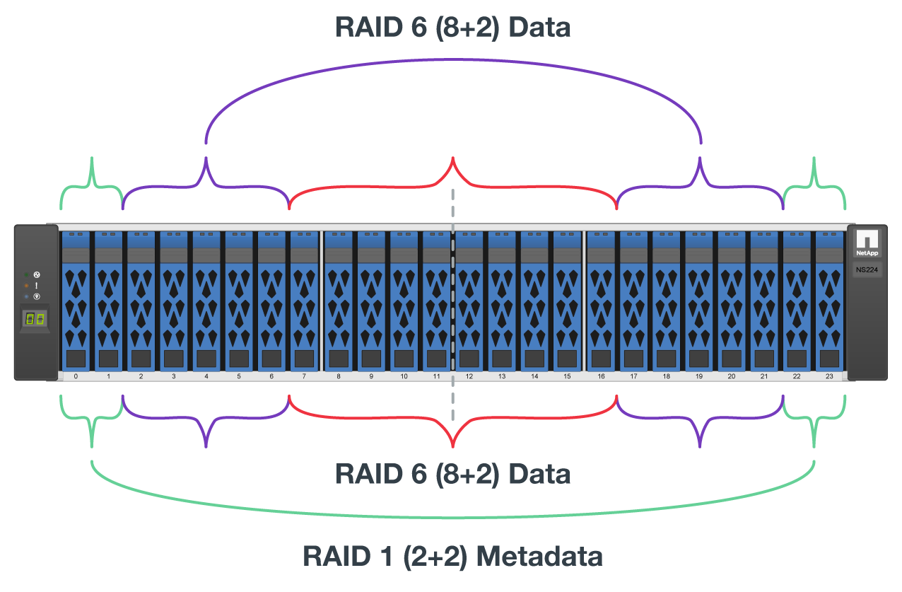
Each EF80 array in a base building block uses all twenty-four NVMe drive slots:
-
4× drives in RAID 1 for MGS/MDT storage (shared volume group or DDP allocation)
-
10× drives in RAID 6 for OST storage (first OST pool)
-
10× drives in RAID 6 for OST storage (second OST pool)
This layout applies when using 3.84 TB, 7.68 TB, or 15.3 TB drives with traditional volume groups. When using 30.7 TB or 61.4 TB Capacity Flash (QLC) drives, provision a single Dynamic Disk Pool across all twenty-four drives and create RAID 1 volumes inside the pool for MGS and MDT volumes, while using default RAID 6 volumes for OSTs.

|
1.92 TB drives are not currently recommended for this solution. Use one of the validated drive capacities listed above. |
Volume and target counts (base building block)
The following table lists MGS, MDT, and OST counts for a base building block.
| Target type | Count per BB | RAID / pool | Notes |
|---|---|---|---|
MGS |
1 |
RAID 1 |
Base building block only; array 1 |
MDT |
8 |
RAID 1 |
4 per array |
OST |
32 |
RAID 6 (TLC) or DDP (QLC) |
16 per array |
Use the following volume sizing guidelines as a starting point in the Ansible inventory.
| Volume | Recommended size | Notes |
|---|---|---|
MGS |
5–10 GiB |
Configuration data only |
MDT |
RAID 1 capacity ÷ MDT count |
Approximately 1–2 TiB each (typical) |
OST |
RAID 6 or DDP capacity ÷ OST count per pool |
Scales with drive capacity; see Sizing guidance |
Primary building block volume distribution
The following figure shows preferred Lustre target placement and NVMe-oF connectivity across OSS/MDS server nodes and E-Series arrays in a base EF80 building block. The diagram labels the management target as MGT (management target); one MGT hosts the MGS (management server) service referenced elsewhere in this document.
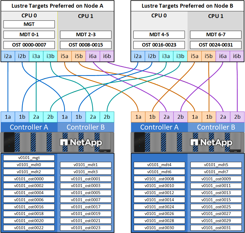
The following table lists how the volumes are distributed across the two arrays and which server each target prefers.
| Target type | Array 1 | Array 2 | Server 1 | Server 2 | Notes |
|---|---|---|---|---|---|
MGS |
1 |
0 |
1 |
0 |
Base building block only |
MDT |
4 |
4 |
4 |
4 |
Each server prefers 2 MDTs from each array |
OST |
16 |
16 |
16 |
16 |
8 per RAID 6 pool × 2 pools per array, or equivalent DDP allocation |
Total volumes |
21 |
20 |
21 |
20 |
Storage pool selection: TLC vs QLC
Choose the E-Series pool type based on the NVMe drive capacity in the arrays:
-
3.84 TB, 7.68 TB, and 15.3 TB drives: Use RAID 6 volume groups for OST volumes and RAID 1 volume groups for MGS and MDT volumes, or use DDP for the shared drive pool.
-
30.7 TB and 61.4 TB Capacity Flash (QLC) drives: Use Dynamic Disk Pools (DDP) only. Create RAID 1 volumes inside the DDP for MGS and MDT storage. Create RAID 6 volumes for OST storage from the DDP.
For per-building-block usable capacity estimates by drive size and layout, see Sizing guidance.
Network requirements
Backend (NVMe-oF)
-
NVMe/InfiniBand or NVMe/RoCE between each OSS/MDS node and each E-Series array
-
MTU 9000 on NVMe/RoCE backend interfaces (typical)
-
Eight paths from each Lustre node to the storage arrays (four to each array)
-
EF80 uses six HCAs per node (i2, i3, i5, and i6 for NVMe-oF; i1 and i4 for LNet). Cable Node A to controller ports whose labels end in
a, such as1aand2a. Cable Node B to controller ports whose labels end inb, such as1band2b. See EF80 six-HCA backend cabling.
Frontend (LNet)
-
IPoIB or RoCE for LNet (
@o2ibnetwork type) -
MTU 9000 on RoCE frontend interfaces (typical)
-
Multi-rail LNet recommended when four frontend ports are available (EF80: i1 and i4 HCAs, both ports)
-
Dedicated InfiniBand or RoCE switch fabric connecting the OSS/MDS server nodes and Lustre clients
-
Lossless RoCE (PFC) recommended on RoCE fabrics
Management
-
Out-of-band management network for server BMCs and array management ports
-
Dedicated Corosync network or shared frontend fabric (site-dependent)