Physical switch configuration
 Suggest changes
Upstream physical switch configuration details based on single-switch and multi-switch environments.
Careful consideration should be taken when making connectivity decisions from the virtual switch layer to physical switches. Separation of internal cluster traffic from external data services should extend to the upstream physical networking layer through isolation provided by layer-2 VLANs.
Physical switch ports should be configured as trunkports. ONTAP Select external traffic can be separated across multiple layer-2 networks in one of two ways. One method is by using ONTAP VLAN-tagged virtual ports with a single port group. The other method is by assigning separate port groups in VST mode to management port e0a. You must also assign data ports to e0b and e0c/e0g depending on the ONTAP Select release and the single-node or multinode configuration. If the external traffic is separated across multiple layer-2 networks, the uplink physical switch ports should have those VLANs in its allowed VLAN list.
ONTAP Select internal network traffic occurs using virtual interfaces defined with link local IP addresses. Because these IP addresses are non-routable, internal traffic between cluster nodes must flow across a single layer-2 network. Route hops between ONTAP Select cluster nodes are unsupported.
Shared physical switch
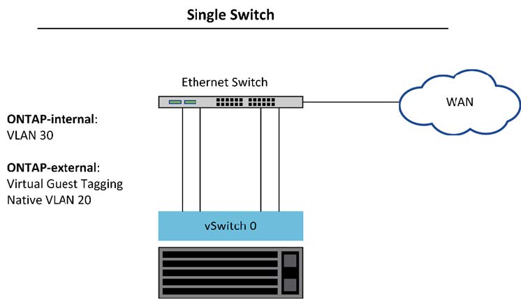
The following figure depicts a possible switch configuration used by one node in a multinode ONTAP Select cluster. In this example, the physical NICs used by the vSwitches hosting both the internal and external network port groups are cabled to the same upstream switch. Switch traffic is kept isolated using broadcast domains contained within separate VLANs.

|
For the ONTAP Select internal network, tagging is done at the port group level. While the following example uses VGT for the external network, both VGT and VST are supported on that port group. |
Network configuration using shared physical switch
|
|
In this configuration, the shared switch becomes a single point of failure. If possible, multiple switches should be used to prevent a physical hardware failure from causing a cluster network outage. |
Multiple physical switches
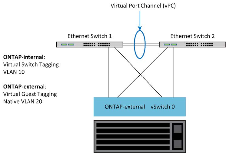
When redundancy is needed, multiple physical network switches should be used. The following figure shows a recommended configuration used by one node in a multinode ONTAP Select cluster. NICs from both the internal and external port groups are cabled into different physical switches, protecting the user from a single hardware-switch failure. A virtual port channel is configured between switches to prevent spanning tree issues.
Network configuration using multiple physical switches