

Replace node2 AFF A700 or FAS9000 controller and NVRAM modules
 Suggest changes
Replace the node2 AFF A700 or FAS9000 controller and NVRAM modules with ASA A900, AFF A900, or FAS9500 controller and NVRAM modules.
At this stage, node2 is down and all data is served by node1. You must take care to remove only the node2 controller module and the node2 NVRAM module. Typically, node2 is controller B located on the right side of the chassis when looking at the controllers from the rear of the system. The controller label is located on the chassis directly above the controller module.

|
Don't power off the chassis because node1 and node2 are in the same chassis and connected to the same power supplies. |
If you are not already grounded, correctly ground yourself.
Step 1: Remove the AFF A700 or FAS9000 controller module
Detach and remove the node2 AFF A700 or FAS9000 controller module.
-
Detach the console cable, if any, and the management cable from the node2 controller module.

When you are working on node2, you only remove the console and e0M cables from node2. You must not remove or change any other cables or connections on either node1 or node2 during this process. -
Unlock and remove the controller module A from the chassis.
-
Slide the orange button on the cam handle downward until it unlocks.
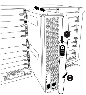

Cam handle release button

Cam handle
-
Rotate the cam handle so that it completely disengages the controller module from the chassis, and then slide the controller module out of the chassis.
Make sure that you support the bottom of the controller module as you slide it out of the chassis.
-
Step 2: Remove the AFF A700 or FAS9000 NVRAM module
Unlock and remove the node2 AFF A700 or FAS9000 NVRAM module.

|
The AFF A700 or FAS9000 NVRAM module is in slot 6 and is double the height of the other modules in the system. |
-
Unlock and remove the NVRAM module from slot 6 of node2.
-
Depress the lettered and numbered cam button.
The cam button moves away from the chassis.
-
Rotate the cam latch down until it is in a horizontal position.
The NVRAM module disengages from the chassis and moves a few inches.
-
Remove the NVRAM module from the chassis by pulling on the pull tabs on the sides of the module face.
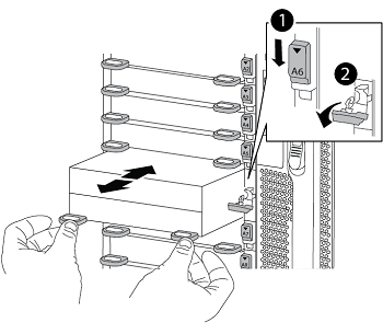
Lettered and numbered I/O cam latch
I/O latch completely unlocked
-
Step 3: Install the ASA A900, AFF A900, or FAS9500 NVRAM module
Install the ASA A900, AFF A900, or FAS9500 NVRAM module in slot 6 of node2.
|
|
|
-
Align the NVRAM module with the edges of the chassis opening in slot 6.
-
Gently slide the NVRAM module into the slot until the lettered and numbered I/O cam latch begins to engage with the I/O cam pin, and then push the I/O cam latch all the way up to lock the NVRAM module in place.
Step 4: Install the ASA A900, AFF A900, or FAS9500 controller module
Install, cable, and connect the ASA A900, AFF A900, or FAS9500 controller module in node2.
-
Align the end of the controller module with bay B in the chassis, and then gently push the controller module halfway into the system.

The bay label is located on the chassis directly above the controller module.
Don't completely insert the controller module in the chassis until you are instructed to do so later in the procedure. -
Cable the management and console ports to the node2 controller module.
Because the chassis is already powered ON, node2 starts booting as soon as it is fully seated. To avoid node2 booting, it is recommended that you connect the console and management cables to the node2 controller module before completely inserting the controller module into the slot. -
Firmly push the controller module into the chassis until it meets the midplane and is fully seated.
The locking latch rises when the controller module is fully seated.
To avoid damaging the connectors, don't use excessive force when sliding the controller module into the chassis. -
Connect the serial console as soon as the module is seated and be ready to interrupt AUTOBOOT of node2.
-
After you interrupt AUTOBOOT, node2 stops at the LOADER prompt. If you do not interrupt AUTOBOOT on time and node2 starts booting, wait for the prompt and enter Ctrl-C to go into the boot menu. After the node stops at the boot menu, use option
8to reboot the node and interrupt AUTOBOOT during reboot. -
At the LOADER> prompt of node2, set the default environment variables:
set-defaults -
Save the default environment variables settings:
saveenv
After installing the ASA A900, AFF A900, or FAS9500 NVRAM and controller modules, netboot node2.