

Replace node2 AFF A220, AFF A200, AFF C190, FAS2620, or FAS2720 controller module
 Suggest changes
Replace the node2 AFF A220, AFF A200, AFF C190, FAS2620, or FAS2720 controller module with an ASA A150, AFF A150, or FAS2820 controller module.
At this stage, node2 is down and all data is served by node1. You must take care to remove only the node2 controller module. Typically, node2 is controller B located on the right side of the chassis when looking at the controllers from the rear of the system. The controller label is located on the chassis directly above the controller module.

|
Don't power off the chassis because node1 and node2 are in the same chassis and connected to the same power supplies. |
If you are not already grounded, correctly ground yourself.
Step 1: Remove the AFF A220, AFF A200, AFF C190, FAS2620, or FAS2720 controller module
To access components inside the node2 controller, remove the controller module from the system and then remove the cover on the controller module.
-
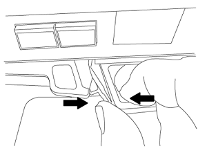
Loosen the hook and loop strap binding the cables to the cable management device, and then unplug the system cables and SFPs (if needed) from the controller module, keeping track of where the cables were connected.
Leave the cables in the cable management device so that when you reinstall the cable management device, the cables are organized.
-
Remove and set aside the cable management devices from the left and right sides of the controller module.
-
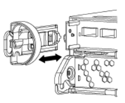
Squeeze the latch on the cam handle until it releases, open the cam handle fully to release the controller module from the midplane, and then, using two hands, pull the controller module out of the chassis.
-
Turn the controller module over and place it on a flat, stable surface.
Step 2: Install the ASA A150, AFF A150, or FAS2820 controller module
Install the ASA A150, AFF A150, or FAS2820 controller module that you received for the upgrade in node2.
-
If you are not already grounded, correctly ground yourself.
-
Disconnect all the cables, including console, management, SAS storage, and data network cables, from the controller being removed.
-
Align the end of the controller module with bay B in the chassis, and then gently push the controller module halfway into the system.

Bay B is located on the right side of the chassis. 
Don't completely insert the controller module in the chassis until you are instructed to do so later in the procedure. -
Cable the management and console ports to the node2 controller module.

Because the chassis is already powered ON, node2 starts booting as soon as it is fully seated. To prevent node2 from booting, connect the console and management cables before fully inserting the controller module. -
Firmly push the controller module into the chassis until it meets the midplane and is fully seated.
The locking latch rises when the controller module is fully seated.
To avoid damaging the connectors, don't use excessive force when sliding the controller module into the chassis. -
Connect the serial console as soon as the module is seated and be ready to interrupt AUTOBOOT of node2.
-
After you interrupt AUTOBOOT, node2 stops at the LOADER prompt. If you do not interrupt AUTOBOOT on time and node2 starts booting, wait for the prompt and enter Ctrl-C to go into the boot menu. After the node stops at the boot menu, use option
8to reboot the node and interrupt AUTOBOOT during reboot.
After installing the ASA A150, AFF A150, or FAS2820 controller module, netboot node2.