

Replace node2 AFF A250 or AFF C250 controller module
 Suggest changes
Replace the node2 AFF A250 or AFF C250 controller module with an AFF A30, AFF A50, AFF C30, or AFF C60 controller module.
At this stage, node2 is down and all data is served by node1. You must take care to remove only the node2 controller module. Typically, node2 is controller B located in the bottom half of the chassis when looking at the controllers from the rear of the system. The controller label is located on the chassis directly above the controller module.

|
Don't power off the chassis because node1 and node2 are in the same chassis and connected to the same power supplies. |
Step 1: Remove the AFF A250 or AFF C250 controller module
To remove the node2 controller module, remove the cable management device and unlock the locking latches. Then, remove the controller module from the chassis.
If you are not already grounded, correctly ground yourself.
-
Insert your forefinger into the latching mechanism on either side of the controller module, press the lever with your thumb, and gently pull the controller a few inches out of the chassis.

If you have difficulty removing the controller module, place your index fingers through the finger holes from the inside (by crossing your arms). 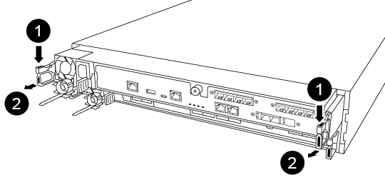

Lever

Latching mechanism
-
Go to the rear of the chassis.
-
Unplug the node2 controller module power supply from the source.
-
Release the power cable retainers, and then unplug the cables from the power supplies for node2.
The power connections for node1 and node2 are on top of each other. Take care to only unplug the cables for node2. Unplugging the cables for node1 and node2 could cause a power outage to both nodes in the HA pair. -
Loosen the hook and loop strap binding the cables to the cable management device, and then unplug the system cables and SFP and QSFP modules (if needed) from the controller module, keeping track of where the cables were connected.
Leave the cables in the cable management device so that when you reinstall the cable management device, the cables are organized.
-
Remove the cable management device from the controller module and set it aside.
-
Press down on both of the locking latches, and then rotate both latches downward at the same time.
The controller module moves slightly out of the chassis.
-
Using both hands, grasp the controller module sides and gently pull it out of the chassis and set it on a flat, stable surface.
Make sure that you support the weight of the controller module as you slide it out of the chassis.
Step 2: Install the AFF A30, AFF A50, AFF C30, or AFF C60 controller module
Install the replacement controller module that you received for the upgrade on node2.
-
Position the storage system onto the rails in the middle of the cabinet or telco rack, and then support the storage system from the bottom and slide it into place.
Don't completely insert the controller module in the chassis until instructed to do so later in the procedure. -
Cable the management and console ports to the node2 controller module.
Because the chassis is already powered ON, node2 starts BIOS initialization followed by AUTOBOOT as soon as it is fully seated. To interrupt the node2 boot, before completely inserting the controller module into the slot, it is recommended that you connect the serial console and management cables to the node2 controller module. -
With the cam handle in the open position, firmly push the controller module in until it meets the midplane and is fully seated. The locking latch rises when the controller module is fully seated. Close the cam handle to the locked position.
To avoid damaging the connectors, don't use excessive force when sliding the controller module into the chassis. -
Connect the serial console as soon as the module is seated and be ready to interrupt AUTOBOOT of node2.
-
After you interrupt AUTOBOOT, node2 stops at the LOADER prompt. If you do not interrupt AUTOBOOT on time and node2 starts booting, wait for the prompt and press Ctrl-C to go into the boot menu. After the node stops at the boot menu, use option
8to reboot the node and interrupt AUTOBOOT during reboot. -
At the LOADER> prompt of node2, set the default environment variables:
set-defaults -
Save the default environment variables settings:
saveenv -
For two-node switchless configurations, verify that you have an X60132A, 4-port 10/25 GbE card in slot1 on node2. The X60132A card is required for cluster interconnect during the upgrade.
After installing the AFF A30, AFF A50, AFF C30, or AFF C60 module, netboot node2.