

Move and replace hardware - AFF A150
 Suggest changes
Move the power supplies, hard drives, and controller module or modules from the impaired chassis to the new chassis, and swap out the impaired chassis from the equipment rack or system cabinet with the new chassis of the same model as the impaired chassis.
Step 1: Move a power supply
Moving out a power supply when replacing a chassis involves turning off, disconnecting, and removing the power supply from the old chassis and installing and connecting it on the replacement chassis.
-
If you are not already grounded, properly ground yourself.
-
Turn off the power supply and disconnect the power cables:
-
Turn off the power switch on the power supply.
-
Open the power cable retainer, and then unplug the power cable from the power supply.
-
Unplug the power cable from the power source.
-
-
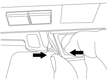
Squeeze the latch on the power supply cam handle, and then open the cam handle to fully release the power supply from the mid plane.
-
Use the cam handle to slide the power supply out of the system.

When removing a power supply, always use two hands to support its weight. -
Repeat the preceding steps for any remaining power supplies.
-
Using both hands, support and align the edges of the power supply with the opening in the system chassis, and then gently push the power supply into the chassis using the cam handle.
The power supplies are keyed and can only be installed one way.

Do not use excessive force when sliding the power supply into the system. You can damage the connector. -
Close the cam handle so that the latch clicks into the locked position and the power supply is fully seated.
-
Reconnect the power cable and secure it to the power supply using the power cable locking mechanism.
Only connect the power cable to the power supply. Do not connect the power cable to a power source at this time.
Step 2: Remove the controller module
Remove the controller module or modules from the old chassis.
-
Loosen the hook and loop strap binding the cables to the cable management device, and then unplug the system cables and SFPs (if needed) from the controller module, keeping track of where the cables were connected.
Leave the cables in the cable management device so that when you reinstall the cable management device, the cables are organized.
-
Remove and set aside the cable management devices from the left and right sides of the controller module.
-
Squeeze the latch on the cam handle until it releases, open the cam handle fully to release the controller module from the midplane, and then, using two hands, pull the controller module out of the chassis.
-
Set the controller module aside in a safe place, and repeat these steps if you have another controller module in the chassis.
Step 3: Move drives to the new chassis
You need to move the drives from each bay opening in the old chassis to the same bay opening in the new chassis.
-
Gently remove the bezel from the front of the system.
-
Remove the drives:
-
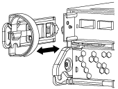
Press the release button at the top of the carrier face below the LEDs.
-
Pull the cam handle to its fully open position to unseat the drive from the midplane, and then gently slide the drive out of the chassis.
The drive should disengage from the chassis, allowing it to slide free of the chassis.
When removing a drive, always use two hands to support its weight.
Drives are fragile. Handle them as little as possible to prevent damage to them.
-
-
Align the drive from the old chassis with the same bay opening in the new chassis.
-
Gently push the drive into the chassis as far as it will go.
The cam handle engages and begins to rotate upward.
-
Firmly push the drive the rest of the way into the chassis, and then lock the cam handle by pushing it up and against the drive holder.
Be sure to close the cam handle slowly so that it aligns correctly with the front of the drive carrier. It click when it is secure.
-
Repeat the process for the remaining drives in the system.
Step 4: Replace a chassis from within the equipment rack or system cabinet
You must remove the existing chassis from the equipment rack or system cabinet before you can install the replacement chassis.
-
Remove the screws from the chassis mount points.
-
With the help of two or three people, slide the old chassis off the rack rails in a system cabinet or L brackets in an equipment rack, and then set it aside.
-
If you are not already grounded, properly ground yourself.
-
Using two or three people, install the replacement chassis into the equipment rack or system cabinet by guiding the chassis onto the rack rails in a system cabinet or L brackets in an equipment rack.
-
Slide the chassis all the way into the equipment rack or system cabinet.
-
Secure the front of the chassis to the equipment rack or system cabinet, using the screws you removed from the old chassis.
-
If you have not already done so, install the bezel.
Step 5: Install the controller
After you install the controller module and any other components into the new chassis, boot it.
For HA pairs with two controller modules in the same chassis, the sequence in which you install the controller module is especially important because it attempts to reboot as soon as you completely seat it in the chassis.
-
Align the end of the controller module with the opening in the chassis, and then gently push the controller module halfway into the system.
Do not completely insert the controller module in the chassis until instructed to do so. -
Recable the console to the controller module, and then reconnect the management port.
-
Repeat the preceding steps if there is a second controller to install in the new chassis.
-
Complete the installation of the controller module:
If your system is in… Then perform these steps… An HA pair
-
With the cam handle in the open position, firmly push the controller module in until it meets the midplane and is fully seated, and then close the cam handle to the locked position.
Do not use excessive force when sliding the controller module into the chassis to avoid damaging the connectors. -
If you have not already done so, reinstall the cable management device.
-
Bind the cables to the cable management device with the hook and loop strap.
-
Repeat the preceding steps for the second controller module in the new chassis.
A stand-alone configuration
-
With the cam handle in the open position, firmly push the controller module in until it meets the midplane and is fully seated, and then close the cam handle to the locked position.
Do not use excessive force when sliding the controller module into the chassis to avoid damaging the connectors. -
If you have not already done so, reinstall the cable management device.
-
Bind the cables to the cable management device with the hook and loop strap.
-
Reinstall the blanking panel and then go to the next step.
-
-
Connect the power supplies to different power sources, and then turn them on.
-
Boot each controller to Maintenance mode:
-
As each controller starts the booting, press
Ctrl-Cto interrupt the boot process when you see the messagePress Ctrl-C for Boot Menu.
If you miss the prompt and the controller modules boot to ONTAP, enter halt, and then at the LOADER prompt enterboot_ontap, pressCtrl-Cwhen prompted, and then repeat this step. -
From the boot menu, select the option for Maintenance mode.
-