

Use F5 DNS to globally load balance StorageGRID
 Suggest changes
By Steve Gorman (F5)
This technical report provides detailed instructions for configuring NetApp StorageGRID with F5 DNS services for global load balancing to deliver better data availability, greater data consistency, and optimize S3 transaction routing when your grid is distributed across multiple sites and/or HA groups.
Introduction
The F5 BIG-IP DNS solution formerly called BIG-IP GTM (Global Traffic Manager) and informally GSLB (Global Server Load Balancing) allows for seamless access across multiple active-active HA groups and active-active multi-site StorageGRID solutions to effectively be realized.
F5 BIG-IP multi-site StorageGRID configuration
Regardless of the number of StorageGRID sites to be supported, a minimum of two BIG-IP appliances, physical or virtual, must have the BIG-IP DNS module enabled and setup. The more DNS appliances, the further the degree of redundancy an enterprise will benefit from.
BIG-IP DNS - First Steps in Initial Set Up
Once the BIG-IP appliance has undergone at least initial provisioning, use a web browser to log into the TMUI (BIG-IP GUI) interface, and choose System → Resource Provisioning. As highlighted, ensure that the “Global Traffic (DNS)” module has a check mark and is shown to be licensed. Note, as in the image, it is common that “Local Traffic (LTM)” can be provisioned on the same appliance.

Configure DNS Protocol Foundational Elements
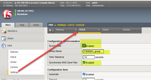
The first step towards global traffic management for StorageGRID sites is to choose the DNS tab, where virtually all the global traffic steering will be configured, and choose Settings→ GLSB. Enable the two synchronization options and choose a DNS group name that will be shared among participating BIG-IP appliances.
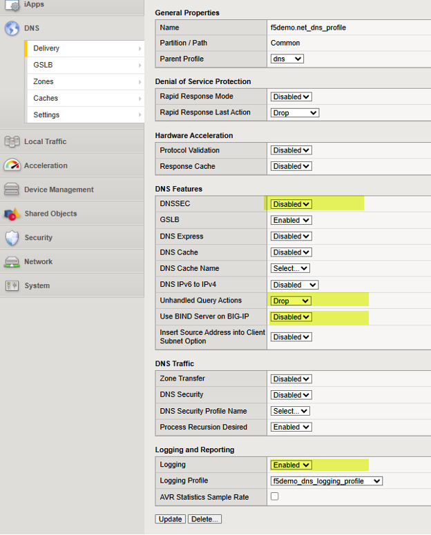
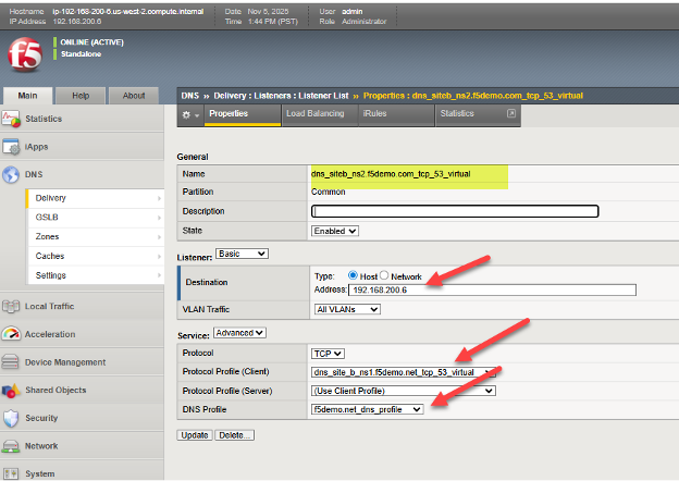
Next, navigate to DNS > Delivery > Profiles > DNS: Create and create a profile that will govern the DNS capabilities you wish to enable or disable. See the previous link for the DNS classroom guide if generation of specific DNS logs are of interest. Here is an example of a working DNS Profile, note the four highlights that represent settings that are important values. For awareness, each possible setting is explained at the following F5 KB (Knowledge Base) article here.
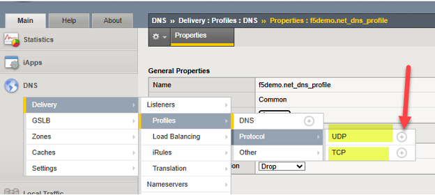
At this point we can adjust the characteristics of the UDP and TCP protocols, through created “profiles”, which can both carry DNS traffic involving BIG-IP. Simply create one new profile for UDP and TCP. Presuming DNS traffic will cross WAN links, a good practice is simply to inherit UDP and TCP characteristics known to perform well in WAN environments.
To add each simply click the “+” icon beside each protocol, and set the parent profile to the following:
UDP → use “parent” profile “udp_gtm_dns”
TCP → use “parent” profile “f5-tcp-wan”
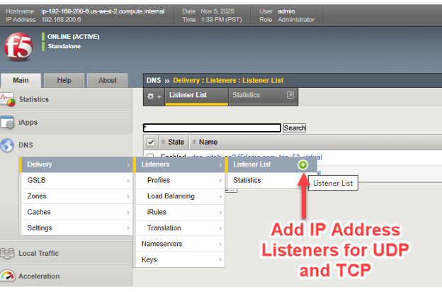
Now, we simply need to assign an IP address for both UDP and TCP traffic involving the BIG-IP DNS. For those familiar with BIG-IP LTM, this is essentially the creation of DNS virtual servers, and virtual servers need “listener” IP addresses.
As in the screenshot, follow the arrows to create listener/virtual servers for DNS/UDP and DNS/TCP.
The following is one example from a live BIG-IP DNS, in it we see the TCP virtual server listener settings and can see how it ties together many of the previous steps. This includes referencing the DNS profile and protocol (TCP) profile, as well as configuring a valid IP address for DNS to use. As with all the objects one creates with BIG-IP, it is helpful to use a meaningful name which serves to self-identify what the object is, such as dns/siteb/TCP53 in the example name assigned.
This concludes the preliminary, typically “one time”, setup steps of a BIG-IP appliance with the DNS module enabled. At this point we are ready to transition to the specifics of setting up a global traffic management solution with our appliances, which will of course be linked to the characteristics of the StorageGRID sites.
Setting up Data Center Sites and Establishing Inter BIG-IP Communications in Four Steps
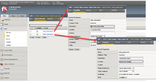
Step one: Create Data Centers
Each site which will house clusters of nodes to be locally load balanced by BIG-IP LTM, should be entered into BIG-IP DNS. This needs to be done on only one BIG-IP DNS, as we are creating a DNS synchronized group to support traffic management, as such this configuration will be shared among DNS members of the group.
Through the TMUI GUI, select DNS > GSLB > Data Centers > Data Center List and create an entry for each of the StorageGRID sites. If using a network setup aligned with Figure 1, DNS appliance located in other non-StorageGRID sites, add Data Centers for these sites in addition to storage sites. In this example sites a and b are created in Ohio and Oregon, the BIG-IPs are dual DNS and LTM appliances.
Step two: Create Servers (List of All BIG-IP Appliances in Solution)
We are now ready to connect the individual StorageGRID site clusters to the BIG-IP DNS setup. Recall, the BIG-IP appliance at each site will do the actual load balancing of S3 traffic, through the configuration of virtual servers that tie a “front-end” reachable IP address/port to a set of back end “pool” of Storage Node appliances, using “back-end” IP addresses/ports.
Should, as one example, all Storage Nodes in a pool be taken offline administratively, perhaps for a site decommissioning, or unexpectedly through real-time failed health checks, traffic will be directed to other sites through altering DNS query responses.
To tie the StorageGrid sites, specifically the local virtual servers, into the BIG-IP DNS configuration on each appliance, the setup need only be done once. The entire group of BIG-IP DNS appliances will have their setups synchronized, in an upcoming step.
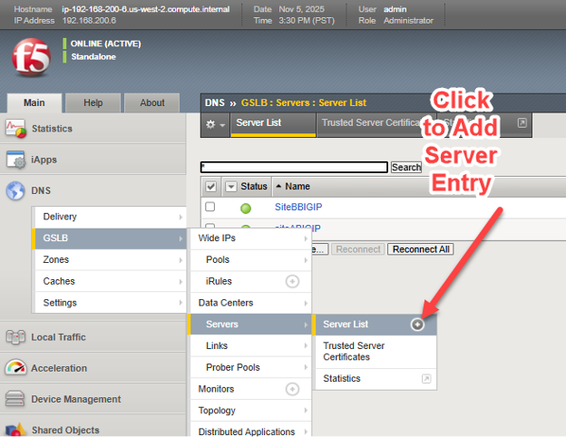
In simple terms, we will create a list, referred to as a server list, of all of our BIG-IP appliances, whether licensed for DNS, LTM or both DNS and LTM. This master list will be sync'd with all BIG-IP DNS appliances upon completion of the list.
On one BIG-IP DNS licensed appliance, choose DNS > GSLB > Servers > Server List and choose the add button (+).
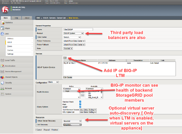
The four key elements when adding each BIG-IP include:
* Selecting BIG-IP from the product pull down, other load balancers are possible but generally lack the real time visibility responsiveness when backend node health deteriorates at each site.
* Add the IP address of the BIG-IP DNS appliance. likely, the first time adding a BIG-IP DNS appliance, the address will be the current GUI-accessed appliance, future appliances will the other appliances in the solution.
* Choose a health monitor, always use “BIG-IP” when the load balancer being added is BIG-IP appliance, for back-end StorageGRID node health consideration.
* Optionally, request virtual server automatic discovery if the appliance is a dual DNS/LTM appliance.
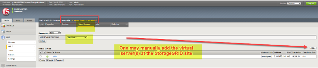
In some situations, such as transient networking problems or firewall ACL rules between network locations, when adding a remote appliance at this stage, the virtual server discovery may not show entries for remote appliances with LTM configured. In such cases, after adding the new appliance (“server”), one can manually add the virtual servers as indicated below. If adding a BIG-IP DNS-only appliance, there will be no virtual servers to be discovered or added to that device.
We need to add these server entries for each appliance in our solution at all sites, including BIG-IP DNS appliances, BIG-IP LTM appliances, and any appliances serving the dual roles of both DNS and LTM units.
Step three: Establish Trust Between all BIG-IP Appliances
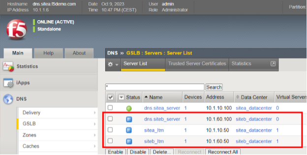
In the following example, four appliances have been added as servers, they are spread across two sites. Note each site has a dedicated BIG-IP DNS and BIG-IP LTM. However, all of the appliances, other than the one currently logged into, are showing blue icons in the “Status” column. This means a trust relationship has not yet been established with the other BIG-IP appliances.
To add trust, SSH into the BIG-IP where the configuration details have just been entered via the GUI, use the “root” account to access the BIG-IP command line interface.
Issue the following singe command at the prompt: bigip_add
The "bigip_add" command pulls the management certificate from the destination BIGIP devices for use during the encrypted “iQuery” channel setup between GSLB servers in the cluster. iQuery, by default, runs using TCP port 4353 and is the hearbeat that allows BOG-IP DNS members to stay in a synchronized state. It makes use of xml and gzip in the encrypted channel. When running "bigip_add" without any options, the command will be run against all BIGIP devices in the GSLB Server list using the current username to connect to the endpoints.
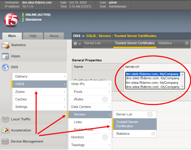
As a quick check of success, simply return to the BIG-IP GUI and confirm all servers now have certificates listed in the displayed pull-down menu.
Step four: Synchronize all BIG-IP DNS Appliances to the DNS Group
The final step will allow all BIG-IP DNS appliances to be fully configured by simply using the TMUI GUI of one single unit. In a sample case, where there are two StorageGRID sites, this means now using SSH to reach the command line of the other site's BIG-IP DNS.
After connecting as root, and ensuring that firewall policies/ACLs allow the two BIG-IP DNS devices to talk on TCP ports 22 (SSH), 443 (HTTPS) and 4354 (F5 iQuery protocol), issue this one command at the prompt: gtm_add <IP address of first site BIG-IP DNS, where all of the GUI steps were previously done>
At this point all further DNS configuration work can be performed on any BIG-IP DNS appliance that has been added to the group. The above command, gtm_add, need not be applied on appliance members that are LTM only. Only appliances supporting DNS require this command to become part of the synchronized DNS group.
Setting up Data Center Sites and Establishing Inter BIG-IP Communications
At this point, all the steps to create the underlying, healthy BIG-IP DNS appliance group is complete. We can now get on with creating names, FQDNs, that point towards our distributed web/S3 services exposed at each StorageGRID datacenter.
These names are referred to as “Wide IPs”, or WIPs for short, and they are normal DNS FQDNs with DNS A resource records. However, rather than pointing at a server like a traditional A resource record, they internally point at pools of BIG-IP virtual servers. Each pool, individually, can be made up of a set of one or more virtual servers. An S3 client requesting an IP address to name resolution will receive the address of the S3 virtual server at the optimal, policy-selected StorageGRID site.
Wide IPs, Pools and Virtual Servers in a Nutshell
To give a simple, fictitious example, a WIP for the name storage.quantumvault.com might see the BIG-IP DNS solution linked with two pools of potential virtual servers. The first pool might be made up of 4 sites in North America; the second pool might consist of 3 sites in Europe.
The selected pool might be arrived at from a range of policy decisions, perhaps a simple ratio of 5:1 could be used to have the bulk of traffic directed to North American StorageGRID sites. More probable perhaps, a topology-based choice where the pool is chosen where, for instance, all European sourced S3 traffic is directed to European sites, and the remainder of world S3 traffic is directed to North American data centers.
Once a pool is arrived at by BIG-IP DNS, let us assume the North American pool was selected, the actual DNS A Resource Record returned to resolve storage.quantumvault.com can be any one of the 4 virtual servers supported by BIG-IP LTM in any of the 4 North American sites. Again, which is chosen is policy driven, simple “static” approaches such as Round-Robin exist, whereas more advanced “dynamic” selections such as performance probes to measure each sites latency from local DNS resolvers is maintained and used as the criteria for site selection.
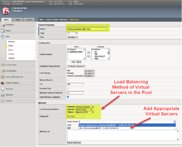
To set a Pool of virtual servers on a BIG-IP DNS, follow the menu path DNS > GSLB > Pools > Pool List > Add (+).
In this example, we can see various North American virtual servers are added to a pool and the preferred approach to load balancing, when this pool is selected, is chosen in a tiered fashion.
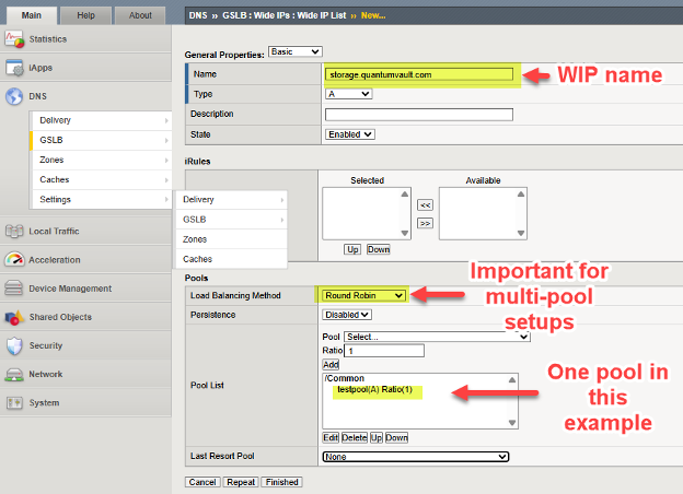
We add the WIP (Wide IP), the name of our service which will be resolved by DNS, to a deployment by following the DNS > GSLB > Wide IPs > Wide IP List > Create (+). In the following example, we provide an example WIP for an S3-enabled storage service.
Adjust DNS to Support Global Traffic Management
At this point all of our underlying BIG-IP appliances are ready to perform GSLB (global server load balancing). We simply need to adjust and assign the names used for S3 traffic flows to leverage the solution.
The general approach is to delegate part of an existing DNS domain of an enterprise to the control of BIG-IP DNS. This is to say to “carve” a section of the name space, a sub-domain, and delegate control of this sub-domain to the BIG-IP DNS appliances. Technically, this is done by ensuring the BIG-IP DNS appliances have A DNS resource records (RRs) in the enterprise DNS and then making these names/addresses Name Server (NS) DNS resource records for the delegated domain.
There are various ways enterprises maintain DNS today, one method is a fully hosted solution. An example of this would be operating and managing DNS through Windows Server 2025. An alternative approach can be for an enterprise to leverage cloud-DNS providers like AWS Route53 or Squarespace.
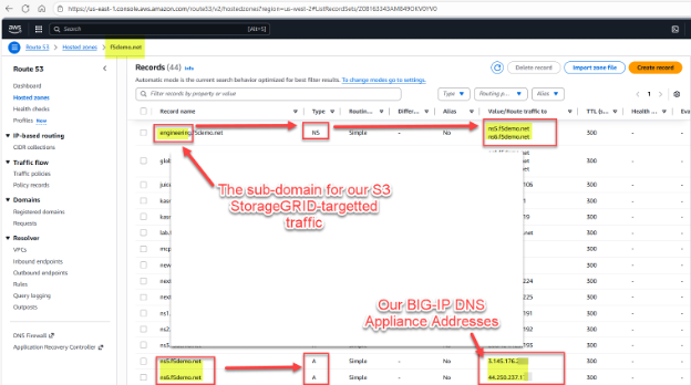
Here is a fictious example for illustration purposes. We have StorageGRID supporting object reads and writes via the S3 protocol with an existing domain managed by AWS Route53, the existing example domain is f5demo.net.
We would like to assign the sub-domain engineering.f5demo.net to the BIG-IP DNS appliances for global traffic management. To do this, we create a new NS (name server) resource record for engineering.f5demo.net and point that to the list of BIG-IP DNS appliance names. In our example, we have two BIG-IP DNS appliances, and as such we create two A resource records for them.
We now, as an example, will set up a Wide IP (WIP) in our BIG-IP DNS, since DNS uses group synchronization, we only need to adjust using the GUI of one appliance. Within the BIG-IP DNS GUI, go to DNS > GSLB > Wide IPs > Wide IP List (+). Recall, in a traditional DNS FQDN setup one would be entering one or more IPv4 addresses, in our case we simply point at one or more pools of StorageGRID virtual servers.
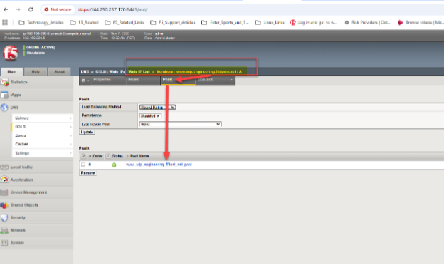
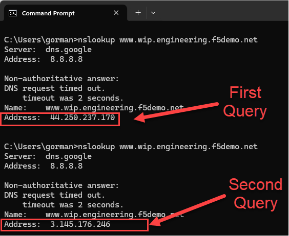
In our example, we have generic web HTTPS servers located in both Ohio and Oregon sites. With a simple “round robin” approach, we should be able to see the global DNS respond to queries for the A resource record mappings for www.wip.engineering.f5demo.net with both virtual server IPs.
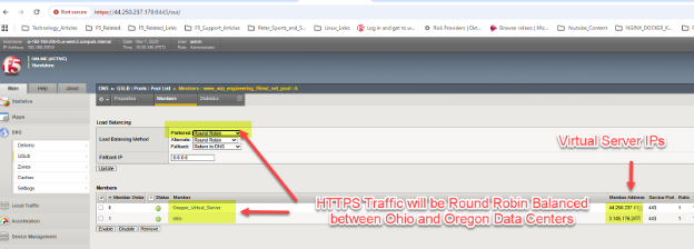
A simple test can be done with web browsers or, in the case of S3 using StorageGRID, perhaps graphical tools like S3Browser. Each DNS query will see the next data center site in the pool used as the target for ensuing traffic, due to our choice of Round Robin within the pool.
In our example setup, we can use dig or nslookup to quickly generate a series of two DNS queries and ensure BIG-IP DNS is indeed doing a round robin load balancing, resulting in both sites receiving traffic over time.
Suggested exploration for more advanced techniques
One of many possible approaches, would use “Global Availability” mode as opposed to the simple “Round Robin” example given above. With Global Availability the sequenced order of pools, or virtual servers within just a single pool, can have traffic directed to it. In this way, all S3 traffic could by default, be directed towards, say, a New York City site.
If health checks indicate an issue with StorageGRID node availability at this site, traffic could at that point be directed to St. Louis. Should St. Louis encounter health concerns, a site in Frankfurt could in turn begin to receive S3 read or write transactions. Thus, global availability is one approach to S3 StorageGRID overall solution resiliency.
Another approach is to mix and match load balancing approaches, where a tiered approach is used.
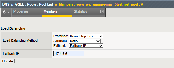
In this example, a “dynamic” option is the first load balancing choice for the sites in the configured pool. In the example shown, an on-going measurement approach using active probing of local DNS resolver performance is maintained and the catalyst for site selection. Should this approach be unavailable, the individual sites can be selected by the ratio assigned to each. With ratio, larger, higher-bandwidth StorageGRID sites can receive more S3 transactions than smaller sites.
Finally, as perhaps a disaster recovery scenario, should all sites in the pool become unhealthy, the specified fallback IP is used as the site of last resort.
One of the more interesting load balancing methods of BIG-IP DNS is “Topology” whereby the incoming source of DNS queries, the S3 user's local DNS resolver, is observed and using Internet topology information the seemingly “closest” site is selected from the pool.
Lastly, if sites span the entire globe, it may be worth considering using the dynamic “probe” technology discussed in detail in the F5 BIG-IP DNS manual. With probes, frequent sources of DNS queries can be monitored, take for example a business-to-business partner whose traffic generally uses the same local DNS resolver. BIG-IP DNS probes can be launched from the BIG-IP LTM in each site around the globe, to determine generally which potential site would likely offer the lowest latency for S3 transactions. As such, traffic from Asian might be better served by Asian StorageGRID sites than sites located in North American or Europe.
Conclusion
The integration of F5 BIG-IP with NetApp StorageGRID addresses technical challenges related to data availability and consistency across multiple sites and optimizing S3 transaction routing. Deploying this solution enhances storage resilience, performance, and reliability, making it ideal for enterprises seeking a robust, scalable, and flexible storage infrastructure.