

更换 node2 AFF A700 或 FAS9000 控制器和 NVRAM 模块
 建议更改
建议更改
用 ASA A900、AFF A900 或 FAS9500 控制器和 NVRAM 模块替换 node2 AFF A700 或 FAS9000 控制器和 NVRAM 模块。
在这个阶段,node2 已关闭,所有数据均由 node1 提供服务。您必须注意仅移除 node2 控制器模块和 node2 NVRAM 模块。通常,从系统后部查看控制器时,node2 是位于机箱右侧的控制器 B。控制器标签位于控制器模块正上方的机箱上。

|
请勿关闭机箱电源、因为node1和node2位于同一机箱中并连接到相同的电源。 |
如果您尚未接地,请正确接地。
步骤 1:卸下 AFF A700 或 FAS9000 控制器模块
拆卸并移除 node2 AFF A700 或 FAS9000 控制器模块。
-
将控制台电缆(如果有)和管理电缆从 node2 控制器模块上拆下。

在 node2 上工作时,只需从 node2 上移除控制台和 e0M 电缆。在此过程中,您不得拆除或更改 node1 或 node2 上的任何其他电缆或连接。 -
解锁控制器模块 A 并将其从机箱中卸下。
-
Slide the orange button on the cam handle downward until it unlocks.
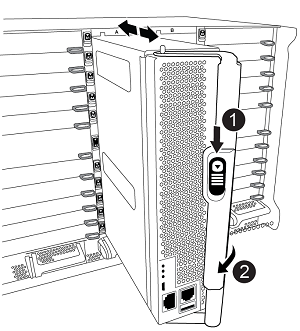

Cam handle release button

Cam handle
-
Rotate the cam handle so that it completely disengages the controller module from the chassis, and then slide the controller module out of the chassis.
Make sure that you support the bottom of the controller module as you slide it out of the chassis.
-
步骤 2:卸下 AFF A700 或 FAS9000 NVRAM 模块
解锁并卸下 node2 AFF A700 或 FAS9000 NVRAM 模块。

|
AFF A700或FAS9000 NVRAM模块位于插槽6中、高度是系统中其他模块的两倍。 |
-
从 node2 的插槽 6 解锁并卸下 NVRAM 模块。
-
Depress the lettered and numbered cam button.
The cam button moves away from the chassis.
-
Rotate the cam latch down until it is in a horizontal position.
NVRAM 模块从机箱中分离并移动几英寸。
-
Remove the NVRAM module from the chassis by pulling on the pull tabs on the sides of the module face.
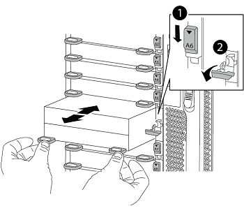
Lettered and numbered I/O cam latch
I/O latch completely unlocked
-
步骤 3:安装 ASA A900、AFF A900 或 FAS9500 NVRAM 模块
将ASA A900、AFF A900或FAS9500 NVRAM模块安装到node2的插槽6中。
|
|
|
-
将 NVRAM 模块与插槽 6 中机箱开口的边缘对齐。
-
将 NVRAM 模块轻轻滑入插槽,直到带字母和编号的 I/O 凸轮闩锁开始与 I/O 凸轮销啮合,然后将 I/O 凸轮闩锁一直向上推,以将 NVRAM 模块锁定到位。
步骤 4:安装 ASA A900、AFF A900 或 FAS9500 控制器模块
在node2中安装ASA A900、AFF A900或FAS9500控制器模块并为其布线和连接。
-
将控制器模块的末端与机箱中的托架 B 对齐,然后将控制器模块轻轻推入系统的一半。

托架标签位于机箱上控制器模块正上方。
请勿将控制器模块完全插入机箱中、直到此过程稍后指示您这样做。 -
使用缆线将管理和控制台端口连接到 node2 控制器模块。
由于机箱已启动,因此 Node2 在完全就位后即开始启动。为了避免 node2 启动,建议在将控制器模块完全插入插槽之前,先将控制台和管理缆线连接到 node2 控制器模块。 -
Firmly push the controller module into the chassis until it meets the midplane and is fully seated.
控制器模块完全就位后,锁定闩锁会上升。
为避免损坏连接器、将控制器模块滑入机箱时不要用力过大。 -
模块就位后立即连接串行控制台并准备中断节点 2 的 AUTOBOOT。
-
中断 AUTOBOOT 后, node2 会在 LOADER 提示符处停止。如果不按时中断 AUTOBOOT 并且 node2 开始启动,请等待提示,然后输入 Ctrl-C 进入启动菜单。节点在启动菜单处停止后,使用选项 `8`重新启动节点,并在重新启动期间中断 AUTOBOOT。
-
在node2的loader>提示符处、设置默认环境变量:
set-defaults -
保存默认环境变量设置:
saveenv
安装 ASA A900、AFF A900 或 FAS9500 NVRAM 和控制器模块后,"网络引导 node2"。