Replace a H610S node
 Suggest changes


You might need to replace the chassis if the fan, central processing unit (CPU), or dual inline memory module (DIMM) fails, or to fix overheating issues or problems with the boot process. The blinking amber LED in the front of the chassis is an indication of a possible need for chassis replacement. You should contact NetApp Support before you proceed.

|
See the KB article for information about installation requirements for H610S nodes. New and spare H610S storage nodes might have additional installation requirements based on the existing Element software version of the storage cluster. Contact NetApp Support for more information. |

|
The terms "node" and "chassis" are used interchangeably in the case of H610S, which is a one rack unit (1U) chassis. |
Best practices for adding and removing drives
You should follow these best practices for adding drives to the cluster:
-
Add all the block drives and ensure that block syncing is complete before you add the slice drives.
-
For Element software 10.x and later, add all the block drives at once. Ensure that you don't this for more than three nodes at once.
-
For Element software 9.x and earlier, add three drives at once allowing them to completely sync before adding the next group of three.
-
Remove the slice drive and ensure that slice syncing is complete before removing the block drives.
-
Remove all the block drives from a single node at once. Ensure that all block syncing is complete before you move on to the next node.
-
You have contacted NetApp Support. If you are ordering a replacement, you should have a case open with NetApp Support.
-
You have obtained the replacement node.
-
You have an electrostatic discharge (ESD) wristband, or you have taken other antistatic protection.
-
If you need to perform the Return to Factory Image (RTFI) process, you have obtained the USB key. NetApp Support can help you decide if you need to perform the RTFI process.
-
You have a keyboard and monitor.
-
You have removed the failed node correctly from the cluster.
-
If a DIMM has failed, you have removed drives before you remove the node from the cluster.
Alarms in the Element UI alert you when a host fails. You must match the serial number of the failed host from the VMware vSphere Web Client with the serial number on the sticker at the back of the node.
-
Locate the service tag at the front of the failed chassis.

-
Verify that the serial number on the service tag matches the NetApp Support case number when you ordered the replacement chassis.
-
Plug in the keyboard and monitor to the back of the failed chassis.
-
Verify the serial number of the failed node with NetApp Support.
-
Power down the chassis.
-
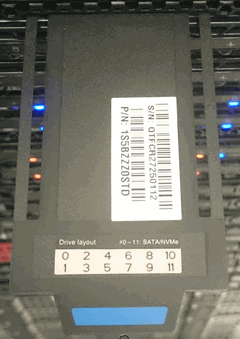
Label the drives in the front and cables at the back with their locations, so that you can put them back in the same locations after the replacement. See the following image for the placement of the drives in the chassis:

-
Remove the cables.
-
Remove the chassis by unscrewing the thumbscrews on the mounting ears. You should package and return the failed chassis to NetApp.
-
Install the replacement chassis.
-
Remove the drives carefully from the failed chassis, and insert them in the replacement chassis.
You should insert the drives in the same slots they were in before you removed them. -
Remove the power supply units from the failed chassis, and insert them in the replacement chassis.
-
Insert the power supply cables, and the network cables in their original ports.
-
Small form-factor pluggable (SFP) transceivers might be inserted in the 10GbE ports of the replacement node. You should remove them before you cable the 10GbE ports.
See your switch vendor's documentation if your switch does not recognize the cables. -
Power on the chassis by pressing the power button at the front. It takes approximately five minutes and 30 seconds for the node to boot.
-
Perform the configuration steps.


