Example configuration: shared FC initiator ports
 Suggest changes


One FC initiator port on an ONTAP system can be connected to up to four target ports on separate storage arrays or, for some storage arrays, to four target ports on the same storage arrays.
The best practice zoning recommendation is to have each FC initiator-target port pair in a separate zone (1:1), even if the same FC initiator is talking to multiple target ports.
Shared FC initiator port attached to multiple targets ports on separate storage arrays
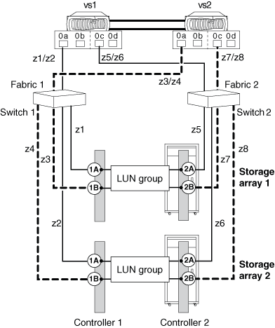
The following illustration shows connections and zoning for sharing an FC initiator port with target ports on different storage arrays.
The solid lines in the following illustration show the connections from the FC initiator ports on system vs1 and the dashed lines show the connections from the FC initiator ports on system vs2.

The following table shows the 1:1 zoning definitions for the example of one FC initiator port sharing multiple target ports on different storage arrays.
| Zone | ONTAP system and FC initiator port | Storage array |
|---|---|---|
Switch 1 |
||
z1 |
vs1:0a |
Storage array 1: Controller 1 Port 1A |
z2 |
vs1:0a |
Storage array 2: Controller 1 Port 1A |
z3 |
vs2:0a |
Storage array 1: Controller 1 Port 1B |
z4 |
vs2:0a |
Storage array 2: Controller 1 Port 1B |
Switch 2 |
||
z5 |
vs1:0c |
Storage array 1: Controller 2 Port 2A |
z6 |
vs1:0c |
Storage array 2: Controller 2 Port 2A |
z7 |
vs2:0c |
Storage array 1: Controller 2 Port 2B |
z8 |
vs2:0c |
Storage array 2: Controller 2 Port 2B |
Shared FC initiator port attached to multiple targets ports on the same storage array
This configuration can be used only with storage arrays whose LUN masking, presentation, or host group capability allows for different LUN group presentations to the same FC initiator based on the target port being accessed.
Some storage arrays can present different sets of logical devices to an FC initiator based on the target port being accessed. These types of storage arrays allow the same FC initiator to be in multiple host groups. On storage arrays with this capability, it is possible for each FC initiator to access multiple array target ports on the same storage array, with each target port presenting a different LUN group to the FC initiator. Check your storage array documentation to determine whether your storage array allows the same FC initiator to be in multiple host groups.
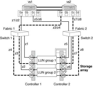
The following illustration shows connections and zoning for sharing an FC initiator port with multiple target ports on the same storage array. In this example, zoning definitions are configured as 1:1, that is, one FC initiator to one target port.
The solid lines in the following illustration show the connections from the FC initiator ports on system vs1 and the dashed lines show the connections from the FC initiator ports on system vs2. Two LUN groups are required for this configuration.

The following table shows the 1:1 zoning definitions for the example of one FC initiator port sharing multiple target ports on the same storage array.
| Zone | ONTAP system and FC initiator port | Storage array and port |
|---|---|---|
Switch 1 |
||
z1 |
vs1:0a |
Controller 1 Port 1A |
z2 |
vs1:0a |
Controller 1 Port 1C |
z3 |
vs2:0a |
Controller 1 Port 1B |
z4 |
vs2:0a |
Controller 1 Port 1D |
Switch 2 |
||
z5 |
vs1:0c |
Controller 2 Port 2A |
z6 |
vs1:0c |
Controller 2 Port 2C |
z7 |
vs2:0c |
Controller 2 Port 2B |
z8 |
vs2:0c |
Controller 2 Port 2D |

