

Replace Broadcom BES-53248 cluster switches with switchless connections
 Suggest changes
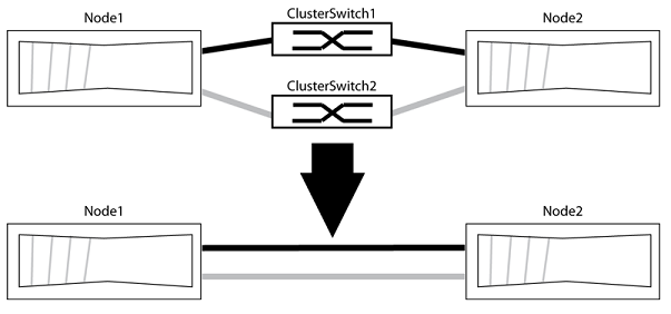
You can migrate from a cluster with a switched cluster network to one where two nodes are directly connected for ONTAP 9.3 and later.
Review requirements
Review the following guidelines:
-
Migrating to a two-node switchless cluster configuration is a nondisruptive operation. Most systems have two dedicated cluster interconnect ports on each node, but you can also use this procedure for systems with a larger number of dedicated cluster interconnect ports on each node, such as four, six or eight.
-
You cannot use the switchless cluster interconnect feature with more than two nodes.
-
If you have an existing two-node cluster that uses cluster interconnect switches and is running ONTAP 9.3 or later, you can replace the switches with direct, back-to-back connections between the nodes.
Make sure you have the following:
-
A healthy cluster that consists of two nodes connected by cluster switches. The nodes must be running the same ONTAP release.
-
Each node with the required number of dedicated cluster ports, which provide redundant cluster interconnect connections to support your system configuration. For example, there are two redundant ports for a system with two dedicated cluster interconnect ports on each node.
Migrate the switches
The following procedure removes the cluster switches in a two-node cluster and replaces each connection to the switch with a direct connection to the partner node.
The examples in the following procedure show nodes that are using "e0a" and "e0b" as cluster ports. Your nodes might be using different cluster ports as they vary by system.
Step 1: Prepare for migration
-
Change the privilege level to advanced, entering
ywhen prompted to continue:set -privilege advancedThe advanced prompt
*>appears. -
ONTAP 9.3 and later supports automatic detection of switchless clusters, which is enabled by default.
You can verify that detection of switchless clusters is enabled by running the advanced privilege command:
network options detect-switchless-cluster showShow example
The following example output shows if the option is enabled.
cluster::*> network options detect-switchless-cluster show
   (network options detect-switchless-cluster show)
Enable Switchless Cluster Detection: true
If "Enable Switchless Cluster Detection" is
false, contact NetApp support. -
If AutoSupport is enabled on this cluster, suppress automatic case creation by invoking an AutoSupport message:
system node autosupport invoke -node * -type all -message MAINT=<number_of_hours>hwhere
his the duration of the maintenance window in hours. The message notifies technical support of this maintenance task so that they can suppress automatic case creation during the maintenance window.In the following example, the command suppresses automatic case creation for two hours:
Show example
cluster::*> system node autosupport invoke -node * -type all -message MAINT=2h
Step 2: Configure ports and cabling
-
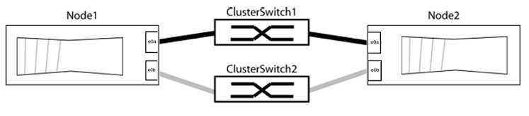
Organize the cluster ports on each switch into groups so that the cluster ports in group1 go to cluster switch1 and the cluster ports in group2 go to cluster switch2. These groups are required later in the procedure.
-
Identify the cluster ports and verify link status and health:
network port show -ipspace ClusterIn the following example for nodes with cluster ports "e0a" and "e0b", one group is identified as “node1:e0a” and “node2:e0a” and the other group as “node1:e0b” and “node2:e0b”. Your nodes might be using different cluster ports because they vary by system.
Verify that the ports have a value of
upfor the “Link” column and a value ofhealthyfor the “Health Status” column.Show example
cluster::> network port show -ipspace Cluster Node: node1 Ignore Speed(Mbps) Health Health Port IPspace Broadcast Domain Link MTU Admin/Oper Status Status ----- --------- ---------------- ----- ----- ----------- ------- ------- e0a Cluster Cluster up 9000 auto/10000 healthy false e0b Cluster Cluster up 9000 auto/10000 healthy false Node: node2 Ignore Speed(Mbps) Health Health Port IPspace Broadcast Domain Link MTU Admin/Oper Status Status ----- --------- ---------------- ----- ----- ----------- ------- ------- e0a Cluster Cluster up 9000 auto/10000 healthy false e0b Cluster Cluster up 9000 auto/10000 healthy false 4 entries were displayed. -
Confirm that all the cluster LIFs are on their home ports.
Verify that the “is-home” column is
truefor each of the cluster LIFs:network interface show -vserver Cluster -fields is-homeShow example
cluster::*> net int show -vserver Cluster -fields is-home
(network interface show)
vserver  lif          is-home
-------- ------------ --------
Cluster  node1_clus1  true
Cluster  node1_clus2  true
Cluster  node2_clus1  true
Cluster  node2_clus2  true
4 entries were displayed.
If there are cluster LIFs that are not on their home ports, revert those LIFs to their home ports:
network interface revert -vserver Cluster -lif * -
Disable auto-revert for the cluster LIFs:
network interface modify -vserver Cluster -lif * -auto-revert false -
Verify that all ports listed in the previous step are connected to a network switch:
network device-discovery show -port cluster_portThe “Discovered Device” column should be the name of the cluster switch that the port is connected to.
Show example
The following example shows that cluster ports "e0a" and "e0b" are correctly connected to cluster switches "cs1" and "cs2".
cluster::> network device-discovery show -port e0a|e0b (network device-discovery show) Node/ Local Discovered Protocol Port Device (LLDP: ChassisID) Interface Platform --------- ------ ------------------------- ---------- ---------- node1/cdp e0a cs1 0/11 BES-53248 e0b cs2 0/12 BES-53248 node2/cdp e0a cs1 0/9 BES-53248 e0b cs2 0/9 BES-53248 4 entries were displayed. -
Verify the connectivity of the remote cluster interfaces:
You can use the network interface check cluster-connectivity command to start an accessibility check for cluster connectivity and then display the details:
network interface check cluster-connectivity start and network interface check cluster-connectivity show
cluster1::*> network interface check cluster-connectivity start
NOTE: Wait for a number of seconds before running the show command to display the details.
cluster1::*> network interface check cluster-connectivity show
                                  Source           Destination      Packet
Node   Date                       LIF              LIF              Loss
------ -------------------------- ---------------- ---------------- -----------
node1
       3/5/2022 19:21:18 -06:00   node1_clus2      node2-clus1      none
       3/5/2022 19:21:20 -06:00   node1_clus2      node2_clus2      none
node2
       3/5/2022 19:21:18 -06:00   node2_clus2      node1_clus1      none
       3/5/2022 19:21:20 -06:00   node2_clus2      node1_clus2      none
For all ONTAP releases, you can also use the cluster ping-cluster -node <name> command to check the connectivity:
cluster ping-cluster -node <name>
cluster1::*> cluster ping-cluster -node local
Host is node2
Getting addresses from network interface table...
Cluster node1_clus1 169.254.209.69 node1 e0a
Cluster node1_clus2 169.254.49.125 node1 e0b
Cluster node2_clus1 169.254.47.194 node2 e0a
Cluster node2_clus2 169.254.19.183 node2 e0b
Local = 169.254.47.194 169.254.19.183
Remote = 169.254.209.69 169.254.49.125
Cluster Vserver Id = 4294967293
Ping status:

Basic connectivity succeeds on 4 path(s)
Basic connectivity fails on 0 path(s)

Detected 9000 byte MTU on 4 path(s):
Local 169.254.47.194 to Remote 169.254.209.69
Local 169.254.47.194 to Remote 169.254.49.125
Local 169.254.19.183 to Remote 169.254.209.69
Local 169.254.19.183 to Remote 169.254.49.125
Larger than PMTU communication succeeds on 4 path(s)
RPC status:
2 paths up, 0 paths down (tcp check)
2 paths up, 0 paths down (udp check)
-
Verify that the cluster is healthy:
cluster ring showAll units must be either master or secondary.
-
Set up the switchless configuration for the ports in group 1.

To avoid potential networking issues, you must disconnect the ports from group1 and reconnect them back-to-back as quickly as possible, for example, in less than 20 seconds. -
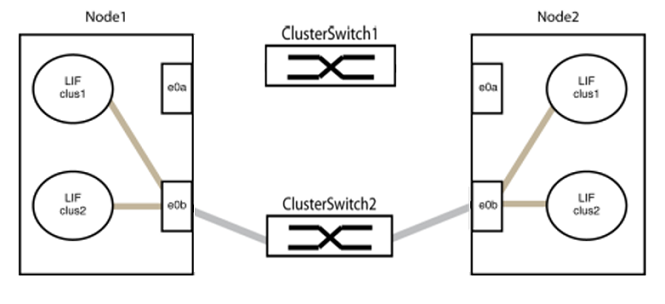
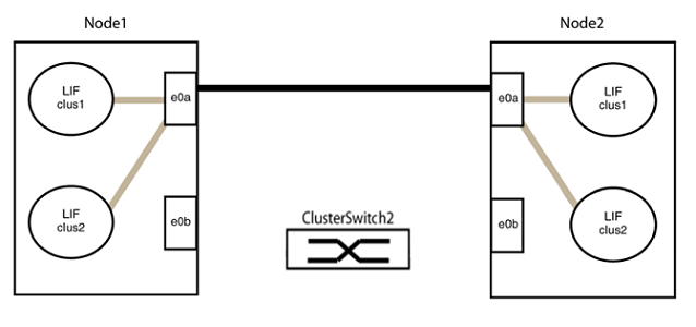
Disconnect all the cables from the ports in group1 at the same time.
In the following example, the cables are disconnected from port "e0a" on each node, and cluster traffic continues through the switch and port "e0b" on each node:
-
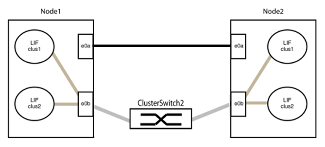
Cable the ports in group1 back-to-back.
In the following example, "e0a" on node1 is connected to "e0a" on node2:
-
-
The switchless cluster network option transitions from
falsetotrue. This might take up to 45 seconds. Confirm that the switchless option is set totrue:network options switchless-cluster showThe following example shows that the switchless cluster is enabled:
cluster::*> network options switchless-cluster show
Enable Switchless Cluster: true
-
Verify the connectivity of the remote cluster interfaces:
You can use the network interface check cluster-connectivity command to start an accessibility check for cluster connectivity and then display the details:
network interface check cluster-connectivity start and network interface check cluster-connectivity show
cluster1::*> network interface check cluster-connectivity start
NOTE: Wait for a number of seconds before running the show command to display the details.
cluster1::*> network interface check cluster-connectivity show
                                  Source           Destination      Packet
Node   Date                       LIF              LIF              Loss
------ -------------------------- ---------------- ---------------- -----------
node1
       3/5/2022 19:21:18 -06:00   node1_clus2      node2-clus1      none
       3/5/2022 19:21:20 -06:00   node1_clus2      node2_clus2      none
node2
       3/5/2022 19:21:18 -06:00   node2_clus2      node1_clus1      none
       3/5/2022 19:21:20 -06:00   node2_clus2      node1_clus2      none
For all ONTAP releases, you can also use the cluster ping-cluster -node <name> command to check the connectivity:
cluster ping-cluster -node <name>
cluster1::*> cluster ping-cluster -node local
Host is node2
Getting addresses from network interface table...
Cluster node1_clus1 169.254.209.69 node1 e0a
Cluster node1_clus2 169.254.49.125 node1 e0b
Cluster node2_clus1 169.254.47.194 node2 e0a
Cluster node2_clus2 169.254.19.183 node2 e0b
Local = 169.254.47.194 169.254.19.183
Remote = 169.254.209.69 169.254.49.125
Cluster Vserver Id = 4294967293
Ping status:

Basic connectivity succeeds on 4 path(s)
Basic connectivity fails on 0 path(s)

Detected 9000 byte MTU on 4 path(s):
Local 169.254.47.194 to Remote 169.254.209.69
Local 169.254.47.194 to Remote 169.254.49.125
Local 169.254.19.183 to Remote 169.254.209.69
Local 169.254.19.183 to Remote 169.254.49.125
Larger than PMTU communication succeeds on 4 path(s)
RPC status:
2 paths up, 0 paths down (tcp check)
2 paths up, 0 paths down (udp check)
|
|
Before proceeding to the next step, you must wait at least two minutes to confirm a working back-to-back connection on group 1. |
-
Set up the switchless configuration for the ports in group 2.
To avoid potential networking issues, you must disconnect the ports from group2 and reconnect them back-to-back as quickly as possible, for example, in less than 20 seconds. -
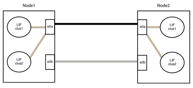
Disconnect all the cables from the ports in group2 at the same time.
In the following example, the cables are disconnected from port "e0b" on each node, and cluster traffic continues through the direct connection between the "e0a" ports:
-
Cable the ports in group2 back-to-back.
In the following example, "e0a" on node1 is connected to "e0a" on node2 and "e0b" on node1 is connected to "e0b" on node2:
-
Step 3: Verify the configuration
-
Verify that the ports on both nodes are correctly connected:
network device-discovery show -port cluster_portShow example
The following example shows that cluster ports "e0a" and "e0b" are correctly connected to the corresponding port on the cluster partner:
cluster::> net device-discovery show -port e0a|e0b (network device-discovery show) Node/ Local Discovered Protocol Port Device (LLDP: ChassisID) Interface Platform ---------- ------ ------------------------- ---------- ---------- node1/cdp e0a node2 e0a AFF-A300 e0b node2 e0b AFF-A300 node1/lldp e0a node2 (00:a0:98:da:16:44) e0a - e0b node2 (00:a0:98:da:16:44) e0b - node2/cdp e0a node1 e0a AFF-A300 e0b node1 e0b AFF-A300 node2/lldp e0a node1 (00:a0:98:da:87:49) e0a - e0b node1 (00:a0:98:da:87:49) e0b - 8 entries were displayed. -
Re-enable auto-revert for the cluster LIFs:
network interface modify -vserver Cluster -lif * -auto-revert true -
Verify that all LIFs are home. This might take a few seconds.
network interface show -vserver Cluster -lif lif_nameShow example
The LIFs have been reverted if the “Is Home” column is
true, as shown fornode1_clus2andnode2_clus2in the following example:cluster::> network interface show -vserver Cluster -fields curr-port,is-home vserver lif curr-port is-home -------- ------------- --------- ------- Cluster node1_clus1 e0a true Cluster node1_clus2 e0b true Cluster node2_clus1 e0a true Cluster node2_clus2 e0b true 4 entries were displayed.
If any cluster LIFS have not returned to their home ports, revert them manually from the local node:
network interface revert -vserver Cluster -lif lif_name -
Check the cluster status of the nodes from the system console of either node:
cluster showShow example
The following example shows epsilon on both nodes to be
false:Node Health Eligibility Epsilon ----- ------- ----------- -------- node1 true true false node2 true true false 2 entries were displayed.
-
Verify the connectivity of the remote cluster interfaces:
You can use the network interface check cluster-connectivity command to start an accessibility check for cluster connectivity and then display the details:
network interface check cluster-connectivity start and network interface check cluster-connectivity show
cluster1::*> network interface check cluster-connectivity start
NOTE: Wait for a number of seconds before running the show command to display the details.
cluster1::*> network interface check cluster-connectivity show
                                  Source           Destination      Packet
Node   Date                       LIF              LIF              Loss
------ -------------------------- ---------------- ---------------- -----------
node1
       3/5/2022 19:21:18 -06:00   node1_clus2      node2-clus1      none
       3/5/2022 19:21:20 -06:00   node1_clus2      node2_clus2      none
node2
       3/5/2022 19:21:18 -06:00   node2_clus2      node1_clus1      none
       3/5/2022 19:21:20 -06:00   node2_clus2      node1_clus2      none
For all ONTAP releases, you can also use the cluster ping-cluster -node <name> command to check the connectivity:
cluster ping-cluster -node <name>
cluster1::*> cluster ping-cluster -node local
Host is node2
Getting addresses from network interface table...
Cluster node1_clus1 169.254.209.69 node1 e0a
Cluster node1_clus2 169.254.49.125 node1 e0b
Cluster node2_clus1 169.254.47.194 node2 e0a
Cluster node2_clus2 169.254.19.183 node2 e0b
Local = 169.254.47.194 169.254.19.183
Remote = 169.254.209.69 169.254.49.125
Cluster Vserver Id = 4294967293
Ping status:

Basic connectivity succeeds on 4 path(s)
Basic connectivity fails on 0 path(s)

Detected 9000 byte MTU on 4 path(s):
Local 169.254.47.194 to Remote 169.254.209.69
Local 169.254.47.194 to Remote 169.254.49.125
Local 169.254.19.183 to Remote 169.254.209.69
Local 169.254.19.183 to Remote 169.254.49.125
Larger than PMTU communication succeeds on 4 path(s)
RPC status:
2 paths up, 0 paths down (tcp check)
2 paths up, 0 paths down (udp check)
-
If you suppressed automatic case creation, reenable it by invoking an AutoSupport message:
system node autosupport invoke -node * -type all -message MAINT=ENDFor more information, see NetApp KB Article 1010449: How to suppress automatic case creation during scheduled maintenance windows.
-
Change the privilege level back to admin:
set -privilege admin
After you've replaced your switches, you can configure switch health monitoring.