

Migrate from older Cisco switches to Cisco Nexus 9336C-FX2 and 9336C-FX2-T switches
 Suggest changes
You can perform a nondisruptive migration from older Cisco cluster switches to Cisco Nexus 9336C-FX2 and 9336C-FX2-T cluster network switches.
Review requirements
Ensure that:
-
You have verified the switch serial number to ensure that the correct switch is migrated.
-
Some of the ports on Nexus 9336C-FX2 switches are configured to run at 10GbE or 40GbE.
-
The 10GbE and 40GbE connectivity from nodes to Nexus 9336C-FX2 cluster switches have been planned, migrated, and documented.
-
The cluster is fully functioning (there should be no errors in the logs or similar issues).
-
Initial customization of the Cisco Nexus 9336C-FX2 switches is complete, so that:
-
9336C-FX2 switches are running the latest recommended version of software.
-
Confirm that Reference Configuration Files (RCFs) have been fully applied to any new switches before migrating the LIFs to the new switches.
-
Check the running and startup configurations on both switches prior to shifting network traffic.
-
Any site customization, such as DNS, NTP, SMTP, SNMP, and SSH, are configured on the new switches.
-
-
You have access to the switch compatibility table on the Cisco Ethernet Switches page for the supported ONTAP, NX-OS, and RCF versions.
-
You have reviewed the appropriate software and upgrade guides available on the Cisco web site for the Cisco switch upgrade and downgrade procedures at Cisco Nexus 9000 Series Switches Support page.

|
If you are changing the port speed of the e0a and e1a cluster ports on AFF A800 or AFF C800 systems, you might observe malformed packets being received after the speed conversion. See Bug 1570339 and the Knowledge Base article CRC errors on T6 ports after converting from 40GbE to 100GbE for guidance. |
Migrate the switches
The examples in this procedure use two nodes. These nodes use two 10GbE cluster interconnect ports e0a and e0b. See the Hardware Universe to verify the correct cluster ports on your platforms. See What additional information do I need to install my equipment that is not in HWU? for more information about switch installation requirements.
|
|
The command outputs might vary depending on the different releases of ONTAP. |
The examples in this procedure use the following switch and node nomenclature:
-
The names of the existing two Cisco switches are cs1 and cs2
-
The new Nexus 9336C-FX2 cluster switches are cs1-new and cs2-new.
-
The node names are node1 and node2.
-
The cluster LIF names are node1_clus1 and node1_clus2 for node 1, and node2_clus1 and node2_clus2 for node 2.
-
The cluster1::>* prompt indicates the name of the cluster.
During this procedure, refer to the following example:
The procedure requires the use of both ONTAP commands and Nexus 9000 Series Switches commands; ONTAP commands are used, unless otherwise indicated.
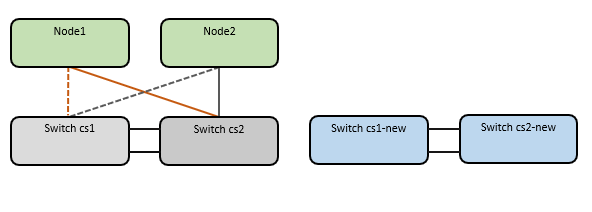
This procedure covers the following scenario:
-
Switch cs2 is replaced by switch cs2-new first.
-
Shut down the ports to the cluster nodes. All ports must be shut down simultaneously to avoid cluster instability.
-
All cluster LIFs fail over to the new switch cs2-new.
-
-
Cabling between the nodes and cs2 are then disconnected from cs2 and reconnected to cs2-new.
-
-
Switch cs1 is replaced by switch cs1-new.
-
Shut down the ports to the cluster nodes. All ports must be shut down simultaneously to avoid cluster instability.
-
All cluster LIFs fail over to the new switch cs1-new.
-
-
Cabling between the nodes and cs1 are then disconnected from cs1 and reconnected to cs1-new.
-
|
|
No operational inter-switch link (ISL) is needed during this procedure. This is by design because RCF version changes can affect ISL connectivity temporarily. To ensure non-disruptive cluster operations, the following procedure fails over all of the cluster LIFs to the operational partner switch while performing the steps on the target switch. |
Step 1: Prepare for migration
-
If AutoSupport is enabled on this cluster, suppress automatic case creation by invoking an AutoSupport message:
system node autosupport invoke -node * -type all -message MAINT=xhwhere x is the duration of the maintenance window in hours.
The AutoSupport message notifies technical support of this maintenance task so that automatic case creation is suppressed during the maintenance window. -
Change the privilege level to advanced, entering y when prompted to continue:
set -privilege advancedThe advanced prompt (*>) appears.
Step 2: Configure ports and cabling
-
On the new switches, confirm that the ISL is cabled and healthy between the switches cs1-new and cs2-new:
show port-channel summaryShow example
cs1-new# show port-channel summary Flags: D - Down P - Up in port-channel (members) I - Individual H - Hot-standby (LACP only) s - Suspended r - Module-removed b - BFD Session Wait S - Switched R - Routed U - Up (port-channel) p - Up in delay-lacp mode (member) M - Not in use. Min-links not met -------------------------------------------------------------------------------- Group Port- Type Protocol Member Ports Channel -------------------------------------------------------------------------------- 1 Po1(SU) Eth LACP Eth1/35(P) Eth1/36(P) cs2-new# show port-channel summary Flags: D - Down P - Up in port-channel (members) I - Individual H - Hot-standby (LACP only) s - Suspended r - Module-removed b - BFD Session Wait S - Switched R - Routed U - Up (port-channel) p - Up in delay-lacp mode (member) M - Not in use. Min-links not met -------------------------------------------------------------------------------- Group Port- Type Protocol Member Ports Channel -------------------------------------------------------------------------------- 1 Po1(SU) Eth LACP Eth1/35(P) Eth1/36(P) -
Display the cluster ports on each node that are connected to the existing cluster switches:
network device-discovery showShow example
cluster1::*> network device-discovery show -protocol cdp Node/ Local Discovered Protocol Port Device (LLDP: ChassisID) Interface Platform ----------- ------ ------------------------- ---------------- ---------------- node1 /cdp e0a cs1 Ethernet1/1 N5K-C5596UP e0b cs2 Ethernet1/2 N5K-C5596UP node2 /cdp e0a cs1 Ethernet1/1 N5K-C5596UP e0b cs2 Ethernet1/2 N5K-C5596UP -
Determine the administrative or operational status for each cluster port.
-
Verify that all the cluster ports are up with a healthy status:
network port show -ipspace ClusterShow example
cluster1::*> network port show -ipspace Cluster Node: node1 Ignore Speed(Mbps) Health Health Port IPspace Broadcast Domain Link MTU Admin/Oper Status Status --------- ------------ ---------------- ---- ---- ----------- -------- ------ e0a Cluster Cluster up 9000 auto/10000 healthy false e0b Cluster Cluster up 9000 auto/10000 healthy false Node: node2 Ignore Speed(Mbps) Health Health Port IPspace Broadcast Domain Link MTU Admin/Oper Status Status --------- ------------ ---------------- ---- ---- ----------- -------- ------ e0a Cluster Cluster up 9000 auto/10000 healthy false e0b Cluster Cluster up 9000 auto/10000 healthy false -
Verify that all the cluster interfaces (LIFs) are on their home ports:
network interface show -vserver ClusterShow example
cluster1::*> network interface show -vserver Cluster Logical Status Network Current Current Is Vserver Interface Admin/Oper Address/Mask Node Port Home ----------- ----------- ---------- ------------------ ----------- ------- ---- Cluster node1_clus1 up/up 169.254.209.69/16 node1 e0a true node1_clus2 up/up 169.254.49.125/16 node1 e0b true node2_clus1 up/up 169.254.47.194/16 node2 e0a true node2_clus2 up/up 169.254.19.183/16 node2 e0b true -
Verify that the cluster displays information for both cluster switches:
system cluster-switch show -is-monitoring-enabled-operational trueShow example
cluster1::*> system cluster-switch show -is-monitoring-enabled-operational true
Switch                      Type               Address          Model
--------------------------- ------------------ ---------------- ---------------
cs1                         cluster-network    10.233.205.92    N5K-C5596UP
      Serial Number: FOXXXXXXXGS
       Is Monitored: true
             Reason: None
   Software Version: Cisco Nexus Operating System (NX-OS) Software, Version
                     9.3(4)
     Version Source: CDP

cs2                         cluster-network     10.233.205.93   N5K-C5596UP
      Serial Number: FOXXXXXXXGD
       Is Monitored: true
             Reason: None
   Software Version: Cisco Nexus Operating System (NX-OS) Software, Version
                     9.3(4)
     Version Source: CDP
-
-
Disable auto-revert on the cluster LIFs.
By disabling auto-revert for this procedure, the cluster LIFs will not automatically move back to their home port. They remain on the current port while it continues to be up and operational.
network interface modify -vserver Cluster -lif * -auto-revert false
Disabling auto-revert ensures ONTAP only fails over the cluster LIFs when the switch ports are shutdown later. -
On cluster switch cs2, shut down the ports connected to the cluster ports of all the nodes in order to fail over the cluster LIFs:
cs2# configure
cs2(config)# interface eth1/1-1/2
cs2(config-if-range)# shutdown
cs2(config-if-range)# exit
cs2(config)# exit
cs2#
-
Verify that the cluster LIFs have failed over to the ports hosted on cluster switch cs1. This might take a few seconds.
network interface show -vserver ClusterShow example
cluster1::*> network interface show -vserver Cluster Logical Status Network Current Current Is Vserver Interface Admin/Oper Address/Mask Node Port Home ----------- ------------- ---------- ------------------ ---------- ------- ---- Cluster node1_clus1 up/up 169.254.3.4/16 node1 e0a true node1_clus2 up/up 169.254.3.5/16 node1 e0a false node2_clus1 up/up 169.254.3.8/16 node2 e0a true node2_clus2 up/up 169.254.3.9/16 node2 e0a false -
Verify that the cluster is healthy:
cluster showShow example
cluster1::*> cluster show
Node       Health  Eligibility   Epsilon
---------- ------- ------------- -------
node1      true    true          false
node2      true    true          false
-
If the cluster LIFs have failed over to switch cs1 and the cluster is healthy, go to Step. 10. If some cluster LIFs are not healthy or the cluster is unhealthy, you can roll back the connectivity to the switch cs2, as follows:
-
Bring up the ports connected to the cluster ports of all the nodes:
cs2# configure
cs2(config)# interface eth1/1-1/2
cs2(config-if-range)# no shutdown
cs2(config-if-range)# exit
cs2(config)# exit
cs2#
-
Verify that the cluster LIFs have failed over to the ports hosted on cluster switch cs1. This might take a few seconds.
network interface show -vserver ClusterShow example
cluster1::*> network interface show -vserver Cluster Logical Status Network Current Current Is Vserver Interface Admin/Oper Address/Mask Node Port Home ----------- ------------- ---------- ------------------ ---------- ------- ---- Cluster node1_clus1 up/up 169.254.3.4/16 node1 e0a true node1_clus2 up/up 169.254.3.5/16 node1 e0a false node2_clus1 up/up 169.254.3.8/16 node2 e0a true node2_clus2 up/up 169.254.3.9/16 node2 e0a false -
Verify that the cluster is healthy:
cluster showShow example
cluster1::*> cluster show
Node       Health  Eligibility   Epsilon
---------- ------- ------------- -------
node1      true    true          false
node2      true    true          false
-
-
Once you have restored LIF and cluster health, restart the process from Step. 4.
-
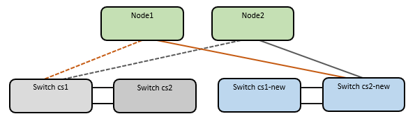
Move all cluster node connection cables from the old cs2 switch to the new cs2-new switch.
Cluster node connection cables moved to the cs2-new switch
-
Confirm the health of the network connections moved to cs2-new:
network port show -ipspace ClusterShow example
cluster1::*> network port show -ipspace Cluster

Node: node1
                                                                       Ignore
                                                  Speed(Mbps) Health   Health
Port      IPspace      Broadcast Domain Link MTU  Admin/Oper  Status   Status
--------- ------------ ---------------- ---- ---- ----------- -------- ------
e0a       Cluster      Cluster          up   9000  auto/10000 healthy  false
e0b       Cluster      Cluster          up   9000  auto/10000 healthy  false

Node: node2
                                                                       Ignore
                                                  Speed(Mbps) Health   Health
Port      IPspace      Broadcast Domain Link MTU  Admin/Oper  Status   Status
--------- ------------ ---------------- ---- ---- ----------- -------- ------
e0a       Cluster      Cluster          up   9000  auto/10000 healthy  false
e0b       Cluster      Cluster          up   9000  auto/10000 healthy  false
All cluster ports that were moved should be up.
-
Check neighbor information on the cluster ports:
network device-discovery show -protocol cdpShow example
cluster1::*> network device-discovery show -protocol cdp

Node/       Local  Discovered
Protocol    Port   Device (LLDP: ChassisID)  Interface      Platform
----------- ------ ------------------------- -------------  --------------
node1      /cdp
            e0a    cs1                       Ethernet1/1    N5K-C5596UP
            e0b    cs2-new                   Ethernet1/1/1  N9K-C9336C-FX2

node2      /cdp
            e0a    cs1                       Ethernet1/2    N5K-C5596UP
            e0b    cs2-new                   Ethernet1/1/2  N9K-C9336C-FX2
Verify that the moved cluster ports see the cs2-new switch as the neighbor.
-
Confirm the switch port connections from switch cs2-new's perspective:
cs2-new# show interface brief
cs2-new# show cdp neighbors
-
On cluster switch cs1, shut down the ports connected to the cluster ports of all the nodes in order to fail over the cluster LIFs.
cs1# configure
cs1(config)# interface eth1/1-1/2
cs1(config-if-range)# shutdown
cs1(config-if-range)# exit
cs1(config)# exit
cs1#
All cluster LIFs fail over to the cs2-new switch.
-
Verify that the cluster LIFs have failed over to the ports hosted on switch cs2-new. This might take a few seconds:
network interface show -vserver ClusterShow example
cluster1::*> network interface show -vserver Cluster Logical Status Network Current Current Is Vserver Interfac Admin/Oper Address/Mask Node Port Home ----------- ------------ ---------- ------------------ ----------- ------- ---- Cluster node1_clus1 up/up 169.254.3.4/16 node1 e0b false node1_clus2 up/up 169.254.3.5/16 node1 e0b true node2_clus1 up/up 169.254.3.8/16 node2 e0b false node2_clus2 up/up 169.254.3.9/16 node2 e0b true -
Verify that the cluster is healthy:
cluster showShow example
cluster1::*> cluster show
Node       Health  Eligibility   Epsilon
---------- ------- ------------- -------
node1      true    true          false
node2      true    true          false
-
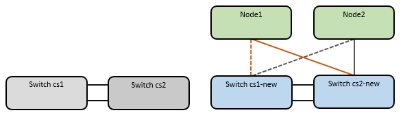
Move the cluster node connection cables from cs1 to the new cs1-new switch.
Cluster node connection cables moved to the cs1-new switch
-
Confirm the health of the network connections moved to cs1-new:
network port show -ipspace ClusterShow example
cluster1::*> network port show -ipspace Cluster

Node: node1
                                                                       Ignore
                                                  Speed(Mbps) Health   Health
Port      IPspace      Broadcast Domain Link MTU  Admin/Oper  Status   Status
--------- ------------ ---------------- ---- ---- ----------- -------- ------
e0a       Cluster      Cluster          up   9000  auto/10000 healthy  false
e0b       Cluster      Cluster          up   9000  auto/10000 healthy  false

Node: node2
                                                                       Ignore
                                                  Speed(Mbps) Health   Health
Port      IPspace      Broadcast Domain Link MTU  Admin/Oper  Status   Status
--------- ------------ ---------------- ---- ---- ----------- -------- ------
e0a       Cluster      Cluster          up   9000  auto/10000 healthy  false
e0b       Cluster      Cluster          up   9000  auto/10000 healthy  false
All cluster ports that were moved should be up.
-
Check neighbor information on the cluster ports:
network device-discovery showShow example
cluster1::*> network device-discovery show -protocol cdp
Node/       Local  Discovered
Protocol    Port   Device (LLDP: ChassisID)  Interface       Platform
----------- ------ ------------------------- --------------  --------------
node1      /cdp
            e0a    cs1-new                   Ethernet1/1/1   N9K-C9336C-FX2
            e0b    cs2-new                   Ethernet1/1/2   N9K-C9336C-FX2

node2      /cdp
            e0a    cs1-new                   Ethernet1/1/1   N9K-C9336C-FX2
            e0b    cs2-new                   Ethernet1/1/2   N9K-C9336C-FX2
Verify that the moved cluster ports see the cs1-new switch as the neighbor.
-
Confirm the switch port connections from switch cs1-new's perspective:
cs1-new# show interface brief
cs1-new# show cdp neighbors
-
Verify that the ISL between cs1-new and cs2-new is still operational:
show port-channel summaryShow example
cs1-new# show port-channel summary
Flags:  D - Down        P - Up in port-channel (members)
        I - Individual  H - Hot-standby (LACP only)
        s - Suspended   r - Module-removed
        b - BFD Session Wait
        S - Switched    R - Routed
        U - Up (port-channel)
        p - Up in delay-lacp mode (member)
        M - Not in use. Min-links not met
--------------------------------------------------------------------------------
Group Port-       Type     Protocol  Member Ports
      Channel
--------------------------------------------------------------------------------
1     Po1(SU)     Eth      LACP      Eth1/35(P)   Eth1/36(P)

cs2-new# show port-channel summary
Flags:  D - Down        P - Up in port-channel (members)
        I - Individual  H - Hot-standby (LACP only)
        s - Suspended   r - Module-removed
        b - BFD Session Wait
        S - Switched    R - Routed
        U - Up (port-channel)
        p - Up in delay-lacp mode (member)
        M - Not in use. Min-links not met
--------------------------------------------------------------------------------
Group Port-       Type     Protocol  Member Ports
      Channel
--------------------------------------------------------------------------------
1     Po1(SU)     Eth      LACP      Eth1/35(P)   Eth1/36(P)
Step 3: Verify the configuration
-
Enable auto-revert on the cluster LIFs.
network interface modify -vserver Cluster -lif * -auto-revert true -
On switch cs2, shut down and restart all cluster ports to trigger an auto-revert of all cluster LIFs that are not on their home ports.
cs2> enable
cs2# configure
cs2(config)# interface eth1/1-1/2
cs2(config-if-range)# shutdown

(Wait for 5-10 seconds before re-enabling the ports)

cs2(config-if-range)# no shutdown

(After executing the no shutdown command, the nodes detect the change and begin to auto-revert the cluster LIFs to their home ports)

cs2(config-if-range)# exit
cs2(config)# exit
cs2#
-
Verify that the cluster LIFs have reverted to their home ports (this might take a minute):
network interface show -vserver ClusterIf any of the cluster LIFs have not reverted to their home port, manually revert them. You must connect to each node-mgmt LIF or SP/BMC system console of the local node that owns the LIF:
network interface revert -vserver Cluster -lif * -
Verify that the cluster is healthy:
cluster show -
Verify the connectivity of the remote cluster interfaces:
You can use the network interface check cluster-connectivity command to start an accessibility check for cluster connectivity and then display the details:
network interface check cluster-connectivity start and network interface check cluster-connectivity show
cluster1::*> network interface check cluster-connectivity start
|
|
Wait for a number of seconds before running the show command to display the details.
|
cluster1::*> network interface check cluster-connectivity show
                                  Source          Destination       Packet
Node   Date                       LIF             LIF               Loss
------ -------------------------- --------------- ----------------- -----------
node1
       3/5/2022 19:21:18 -06:00   node1_clus2      node2_clus1      none
       3/5/2022 19:21:20 -06:00   node1_clus2      node2_clus2      none

node2
       3/5/2022 19:21:18 -06:00   node2_clus2      node1_clus1      none
       3/5/2022 19:21:20 -06:00   node2_clus2      node1_clus2      none
For all ONTAP releases, you can also use the cluster ping-cluster -node <name> command to check the connectivity:
cluster ping-cluster -node <name>
cluster1::*> cluster ping-cluster -node node2
Host is node2
Getting addresses from network interface table...
Cluster node1_clus1 169.254.209.69 node1     e0a
Cluster node1_clus2 169.254.49.125 node1     e0b
Cluster node2_clus1 169.254.47.194 node2     e0a
Cluster node2_clus2 169.254.19.183 node2     e0b
Local = 169.254.47.194 169.254.19.183
Remote = 169.254.209.69 169.254.49.125
Cluster Vserver Id = 4294967293
Ping status:

Basic connectivity succeeds on 4 path(s)
Basic connectivity fails on 0 path(s)
................
Detected 9000 byte MTU on 4 path(s):
    Local 169.254.19.183 to Remote 169.254.209.69
    Local 169.254.19.183 to Remote 169.254.49.125
    Local 169.254.47.194 to Remote 169.254.209.69
    Local 169.254.47.194 to Remote 169.254.49.125
Larger than PMTU communication succeeds on 4 path(s)
RPC status:
2 paths up, 0 paths down (tcp check)
2 paths up, 0 paths down (udp check)
After you've migrated the switches, you can configure switch health monitoring.