

Replace a DIMM - AFF A900
 Suggest changes
You must replace a DIMM in the controller when your storage system encounters errors such as, excessive CECC (Correctable Error Correction Codes) errors that are based on Health Monitor alerts or uncorrectable ECC errors, typically caused by a single DIMM failure preventing the storage system from booting ONTAP.
All other components in the system must be functioning properly; if not, you must contact technical support.
You must replace the failed component with a replacement FRU component you received from your provider.
Step 1: Shut down the impaired controller
Shut down or take over the impaired controller using one of the following options.
Take over and halt the impaired controller so that the healthy controller continues to serve data from the impaired controller's storage. To do this, you suppress automatic case creation in AutoSupport, disable automatic giveback, and bring the impaired controller to the LOADER prompt. The LOADER prompt is the safe halted state from which you can replace the FRU.
-
If you have a SAN system, you must have checked event messages (
cluster kernel-service show) for the impaired controller SCSI blade. Thecluster kernel-service showcommand (from priv advanced mode) displays the node name, quorum status of that node, availability status of that node, and operational status of that node.Each SCSI-blade process should be in quorum with the other nodes in the cluster. Any issues must be resolved before you proceed with the replacement.
-
If you have a cluster with more than two nodes, it must be in quorum. If the cluster is not in quorum or a healthy controller shows false for eligibility and health, you must correct the issue before shutting down the impaired controller; see Synchronize a node with the cluster.
-
If AutoSupport is enabled, suppress automatic case creation by invoking an AutoSupport message:
system node autosupport invoke -node * -type all -message MAINT=<number of hours down>hThis prevents automatic support cases from being opened during your planned maintenance window. The maximum suppression duration is 72 hours. If your maintenance completes early, you can re-enable case creation by invoking an AutoSupport message with
MAINT=END. For more information, see How to suppress automatic case creation during scheduled maintenance windows.The following AutoSupport message suppresses automatic case creation for two hours:
cluster1:> system node autosupport invoke -node * -type all -message MAINT=2h -
Disable automatic giveback:
-
Enter the following command from the console of the healthy controller:
storage failover modify -node impaired_node_name -auto-giveback false -
Enter
ywhen you see the prompt Do you want to disable auto-giveback?
-
-
Take the impaired controller to the LOADER prompt:
If the impaired controller is displaying… Then… The LOADER prompt
Go to the next step.
Waiting for giveback…
Press Ctrl-C, and then respond
ywhen prompted.System prompt or password prompt
Take over or halt the impaired controller from the healthy controller:
storage failover takeover -ofnode impaired_node_name -halt trueThe -halt true parameter brings you to the LOADER prompt.

|
Do not use this procedure if your system is in a two-node MetroCluster configuration. |
Take over and halt the impaired controller so that the healthy controller continues to serve data from the impaired controller's storage. To do this, you suppress automatic case creation in AutoSupport, disable automatic giveback, and bring the impaired controller to the LOADER prompt. The LOADER prompt is the safe halted state from which you can replace the FRU.
-
If you have a cluster with more than two nodes, it must be in quorum. If the cluster is not in quorum or a healthy controller shows false for eligibility and health, you must correct the issue before shutting down the impaired controller; see Synchronize a node with the cluster.
-
If you have a MetroCluster configuration, you must have confirmed that the MetroCluster Configuration State is configured and that the nodes are in an enabled and normal state (
metrocluster node show).
-
If AutoSupport is enabled, suppress automatic case creation by invoking an AutoSupport message:
system node autosupport invoke -node * -type all -message MAINT=<number of hours down>hThis prevents automatic support cases from being opened during your planned maintenance window. The maximum suppression duration is 72 hours. If your maintenance completes early, you can re-enable case creation by invoking an AutoSupport message with
MAINT=END. For more information, see How to suppress automatic case creation during scheduled maintenance windows.The following AutoSupport message suppresses automatic case creation for two hours:
cluster1:*> system node autosupport invoke -node * -type all -message MAINT=2h -
Disable automatic giveback from the console of the healthy controller:
storage failover modify –node local -auto-giveback false -
Take the impaired controller to the LOADER prompt:
If the impaired controller is displaying… Then… The LOADER prompt
Go to the next step.
Waiting for giveback…
Press Ctrl-C, and then respond
ywhen prompted.System prompt or password prompt (enter system password)
Take over or halt the impaired controller from the healthy controller:
storage failover takeover -ofnode impaired_node_nameWhen the impaired controller shows Waiting for giveback…, press Ctrl-C, and then respond
y.
Step 2: Remove the controller module
To access components inside the controller, you must first remove the controller module from the system and then remove the cover on the controller module.
-
If you are not already grounded, properly ground yourself.
-
Unplug the cables from the impaired controller module, and keep track of where the cables were connected.
-
Slide the terra cotta button on the cam handle downward until it unlocks.
Animation - Remove the controller

Cam handle release button

Cam handle
-
Rotate the cam handle so that it completely disengages the controller module from the chassis, and then slide the controller module out of the chassis.
Make sure that you support the bottom of the controller module as you slide it out of the chassis.
-
Place the controller module lid-side up on a stable, flat surface, press the blue button on the cover, slide the cover to the back of the controller module, and then swing the cover up and lift it off of the controller module.

Controller module cover locking button
Step 3: Replace the DIMMs
To replace the DIMMs, locate them inside the controller and follow the specific sequence of steps.
|
|
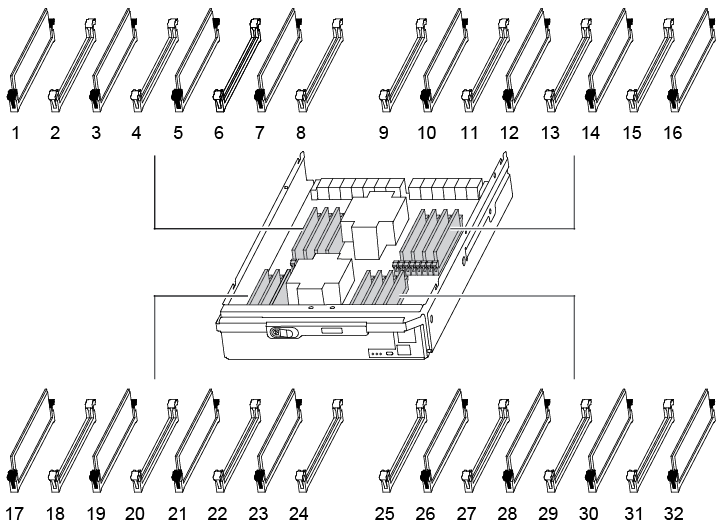
The VER2 controller has fewer DIMM sockets. There is no reduction in the number of DIMMs supported or change in the DIMM socket numbering. When moving the DIMMs to the new controller module, install the DIMMs into the same socket number/location as the impaired controller module. See the FRU map diagram on the VER2 controller module for DIMM socket locations. |
-
If you are not already grounded, properly ground yourself.
-
Locate the DIMMs on your controller module.
-
Eject the DIMM from its slot by slowly pushing apart the two DIMM ejector tabs on either side of the DIMM, and then slide the DIMM out of the slot.

Carefully hold the DIMM by the edges to avoid pressure on the components on the DIMM circuit board. Animation - Replace DIMM
DIMM ejector tabs
DIMM
-
Remove the replacement DIMM from the antistatic shipping bag, hold the DIMM by the corners, and align it to the slot.
The notch among the pins on the DIMM should line up with the tab in the socket.
-
Make sure that the DIMM ejector tabs on the connector are in the open position, and then insert the DIMM squarely into the slot.
The DIMM fits tightly in the slot, but should go in easily. If not, realign the DIMM with the slot and reinsert it.
Visually inspect the DIMM to verify that it is evenly aligned and fully inserted into the slot. -
Push carefully, but firmly, on the top edge of the DIMM until the ejector tabs snap into place over the notches at the ends of the DIMM.
-
Close the controller module cover.
Step 4: Install the controller
After you install the components into the controller module, you must install the controller module back into the system chassis and boot the operating system.
For HA pairs with two controller modules in the same chassis, the sequence in which you install the controller module is especially important because it attempts to reboot as soon as you completely seat it in the chassis.
-
If you are not already grounded, properly ground yourself.
-
If you have not already done so, replace the cover on the controller module.
Controller module cover locking button
-
Align the end of the controller module with the opening in the chassis, and then gently push the controller module halfway into the system.
Animation - Install controller
Cam handle release button
Cam handle
Do not completely insert the controller module in the chassis until instructed to do so. -
Cable the management and console ports only, so that you can access the system to perform the tasks in the following sections.
You will connect the rest of the cables to the controller module later in this procedure. -
Complete the reinstallation of the controller module:
-
If you have not already done so, reinstall the cable management device.
-
Firmly push the controller module into the chassis until it meets the midplane and is fully seated.
The locking latches rise when the controller module is fully seated.
Do not use excessive force when sliding the controller module into the chassis to avoid damaging the connectors. The controller module begins to boot as soon as it is fully seated in the chassis. Be prepared to interrupt the boot process.
-
Rotate the locking latches upward, tilting them so that they clear the locking pins, and then lower them into the locked position.
-
Interrupt the boot process by pressing
Ctrl-Cwhen you see Press Ctrl-C for Boot Menu. -
Select the option to boot to Maintenance mode from the displayed menu.
-
Step 5: Run system-level diagnostics
After installing a new DIMM, you should run diagnostics.
Your system must be at the LOADER prompt to start System Level Diagnostics.
All commands in the diagnostic procedures are issued from the controller where the component is being replaced.
-
If the controller to be serviced is not at the LOADER prompt, perform the following steps:
-
Select the Maintenance mode option from the displayed menu.
-
After the controller boots to Maintenance mode, halt the controller:
haltAfter you issue the command, you should wait until the system stops at the LOADER prompt.
During the boot process, you can safely respond yto prompts.-
If a prompt appears warning that when entering Maintenance mode in an HA configuration, you must ensure that the healthy controller remains down.
-
-
-
At the LOADER prompt, access the special drivers specifically designed for system-level diagnostics to function properly:
boot_diagsDuring the boot process, you can safely respond
yto the prompts until the Maintenance mode prompt (*>) appears. -
Run diagnostics on the system memory:
sldiag device run -dev mem -
Verify that no hardware problems resulted from the replacement of the DIMMs:
sldiag device status -dev mem -long -state failedSystem-level diagnostics returns you to the prompt if there are no test failures, or lists the full status of failures resulting from testing the component.
-
Proceed based on the result of the preceding step:
If the system-level diagnostics tests… Then… Were completed without any failures
-
Clear the status logs:
sldiag device clearstatus -
Verify that the log was cleared:
sldiag device statusThe following default response is displayed:
SLDIAG: No log messages are present.
-
Exit Maintenance mode:
haltThe controller displays the LOADER prompt.
-
Boot the controller from the LOADER prompt:
bye -
Return the controller to normal operation:
If your controller is in… Then… An HA pair
Perform a give back:
storage failover giveback -ofnode replacement_node_nameNote: If you disabled automatic giveback, re-enable it with the storage failover modify command.Resulted in some test failures
Determine the cause of the problem:
-
Exit Maintenance mode:
haltAfter you issue the command, wait until the system stops at the LOADER prompt.
-
Verify that you have observed all the considerations identified for running system-level diagnostics, that cables are securely connected, and that hardware components are properly installed in the storage system.
-
Boot the controller module you are servicing, interrupting the boot by pressing
Ctrl-Cwhen prompted to get to the Boot menu:-
If you have two controller modules in the chassis, fully seat the controller module you are servicing in the chassis.
The controller module boots up when fully seated.
-
If you have one controller module in the chassis, connect the power supplies, and then turn them on.
-
-
Select Boot to maintenance mode from the menu.
-
Exit Maintenance mode by entering the following command:
haltAfter you issue the command, wait until the system stops at the LOADER prompt.
-
Rerun the system-level diagnostic test.
-
Step 6: Return the failed part to NetApp
Return the failed part to NetApp, as described in the RMA instructions shipped with the kit. See the Part Return and Replacements page for further information.