

Replace DIMMs in the E4000 controller in an SG5800
 Suggest changes
You can replace a DIMM in the E4000 if it has failed.
To replace a DIMM, you must verify the cache size of your controller, place the controller offline, remove the controller, remove the DIMMs, and install the new DIMMs in your controller. Then you can bring your controller back online and verify the storage array is working properly.
The appliance Storage Node may not be accessible when you replace the controller. If the E4000 series controller is functioning sufficiently, you can place the SG5800 controller into maintenance mode.
-
Make sure you have the following:
-
A replacement DIMM.
-
An ESD wristband, or you have taken other antistatic precautions.
-
A flat, static free work area.
-
Labels to identify each cable that is connected to the controller canister.
-
-
Access to SANtricity System Manager:
-
From Grid Manager, select Nodes > appliance node > SANtricity System Manager. Controller information is on the SANtricity System Manager tab.

You may not be able to access SANtricity System Manager using Grid Manager during certain steps of this procedure. If the SG5800 controller is shut down, you will need to access SANtricity System Manager using your browser. -
Point a browser in your management station to the controller's domain name or IP address.
-
Step 1: Determine if you need to replace a DIMM
Verify the cache size of your controller before replacing the DIMMS.
-
Access the Storage Array profile for the controller. From SANtricity System Manager, go to Support › Support Center. From the Support Resources page, select Storage Array Profile.
-
Scroll down or use the Search field to locate the Data Cache Module information.
-
If a failed DIMM or a DIMM reporting Data Cache Module as not optimal is present, note the DIMM’s location and continue to replace the DIMMs on your controller.
Step 2: Power down the controller shelf
Power down the controller so you can safely remove and replace the DIMMs.
-
From SANtricity System Manager, review the details in the Recovery Guru to confirm that there is an issue with a mismatched memory and to ensure no other items must be addressed first.
-
From the Details area of the Recovery Guru, determine which DIMM to replace.
-
Back up the storage array’s configuration database using SANtricity System Manager.
If a problem occurs when you remove a controller, you can use the saved file to restore your configuration. The system will save the current state of the RAID configuration database, which includes all data for volume groups and disk pools on the controller.
-
From System Manager:
-
Select Support › Support Center › Diagnostics.
-
Select Collect Configuration Data.
-
Click Collect.
The file is saved in the Downloads folder for your browser with the name, configurationData- <arrayName>-<dateTime>.7z.
-
-
-
Shut down the SG5800 controller.
-
Log in to the grid node:
-
Enter the following command:
ssh admin@grid_node_IP -
Enter the password listed in the
Passwords.txtfile. -
Enter the following command to switch to root:
su - -
Enter the password listed in the
Passwords.txtfile.When you are logged in as root, the prompt changes from
$to#.
-
-
Shut down the SG5800 controller:
shutdown -h now -
Wait for any data in cache memory to be written to the drives.
The green Cache Active LED on the back of the E4000 controller is on when cached data needs to be written to the drives. You must wait for this LED to turn off.
-
-
From the home page of SANtricity System Manager, select View Operations in Progress.
-
Confirm that all operations have completed before continuing with the next step.
-
Turn off both power switches on the controller shelf.
-
Wait for all LEDs on the controller shelf to turn off.
Step 3: Remove controller canister
Remove the controller canister from the system and then remove the controller canister cover.
-
If you are not already grounded, properly ground yourself.
-
Loosen the hook and loop strap binding the cables to the cable management device, and then unplug the system cables and SFPs (if needed) from the controller canister, keeping track of where the cables were connected.
Leave the cables in the cable management device so that when you reinstall the cable management device, the cables are organized.
-
Remove and set aside the cable management devices from the left and right sides of the controller canister.
-
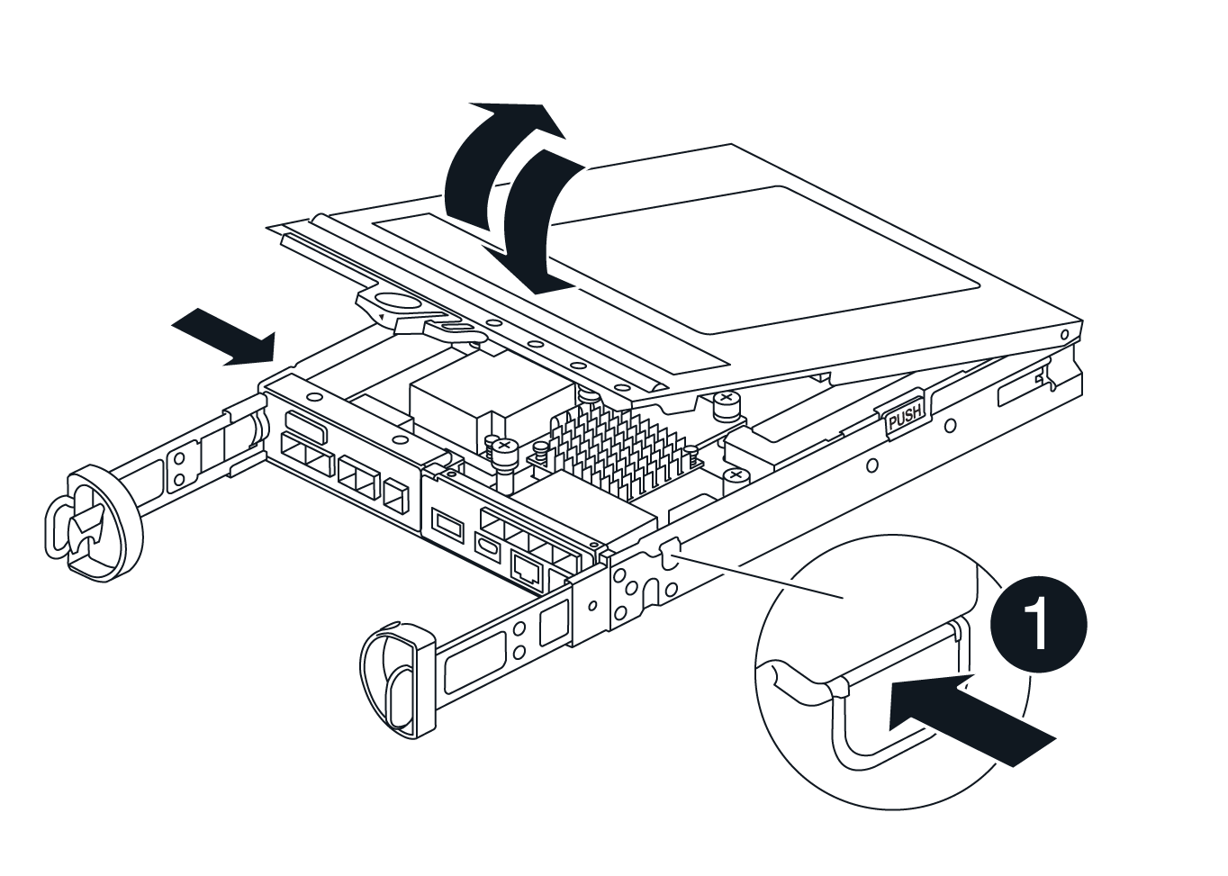
Squeeze the latch on the cam handle until it releases, open the cam handle fully to release the controller canister from the midplane, and then, using two hands, pull the controller canister out of the chassis.
-
Turn the controller canister over and place it on a flat, stable surface.
-
Open the cover by pressing the blue buttons on the sides of the controller canister to release the cover, and then rotate the cover up and off of the controller canister.
Step 4: Replace the DIMMs
Locate the DIMM inside the controller, remove it, and replace it.
-
If you are not already grounded, properly ground yourself.
-
You must perform a clean system shutdown before replacing system components to avoid losing unwritten data in the nonvolatile memory (NVMEM). The LED is located on the back of the controller canister.
-
If the NVMEM LED is not flashing, there is no content in the NVMEM; you can skip the following steps and proceed to the next task in this procedure.
-
If the NVMEM LED is flashing, there is data in the NVMEM and you must disconnect the battery to clear the memory:
-
Remove the battery from the controller canister by pressing the blue button on the side of the controller canister.
-
Slide the battery up until it clears the holding brackets, and then lift the battery out of the controller canister.
-
Locate the battery cable, press the clip on the battery plug to release the lock clip from the plug socket, and then unplug the battery cable from the socket.
-
Confirm that the NVMEM LED is no longer lit.
-
Reconnect the battery connector and recheck the LED on the back of the controller.
-
Unplug the battery cable.
-
-
Locate the DIMMs on your controller canister.
-
Note the orientation and location of the DIMM in the socket so that you can insert the replacement DIMM in the proper orientation.
-
Eject the DIMM from its slot by slowly pushing apart the two DIMM ejector tabs on either side of the DIMM, and then slide the DIMM out of the slot.
The DIMM will rotate up a little.
-
Rotate the DIMM as far as it will go, and then slide the DIMM out of the socket.
Carefully hold the DIMM by the edges to avoid pressure on the components on the DIMM circuit board. 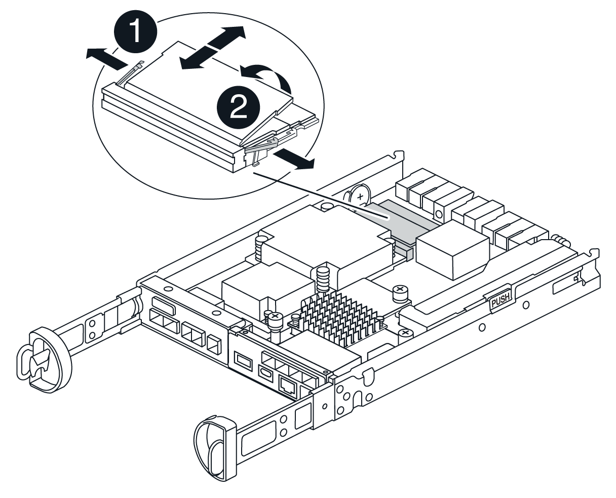

DIMM ejector tabs

DIMMS
-
Remove the replacement DIMM from the antistatic shipping bag, hold the DIMM by the corners, and align it to the slot.
The notch among the pins on the DIMM should line up with the tab in the socket.
-
Insert the DIMM squarely into the slot.
The DIMM fits tightly in the slot, but should go in easily. If not, realign the DIMM with the slot and reinsert it.
Visually inspect the DIMM to verify that it is evenly aligned and fully inserted into the slot. -
Push carefully, but firmly, on the top edge of the DIMM until the ejector tabs snap into place over the notches at the ends of the DIMM.
-
Reconnect the battery:
-
Plug in the battery.
-
Make sure that the plug locks down into the battery power socket on the motherboard.
-
Align the battery with the holding brackets on the sheet metal side wall.
-
Slide the battery pack down until the battery latch engages and clicks into the opening on the side wall.
-
-
Reinstall the controller canister cover.
Step 5: Reinstall the controller canister
Reinstall the controller canister into the chassis.
-
If you are not already grounded, properly ground yourself.
-
If you have not already done so, replace the cover on the controller canister.
-
Turn the controller canister over and align the end with the opening in the chassis.
-
Gently push the controller canister halfway into the system. Align the end of the controller canister with the opening in the chassis, and then gently push the controller canister halfway into the system.
Do not completely insert the controller canister in the chassis until instructed to do so. -
Recable the system, as needed.
-
Complete the reinstallation of the controller canister:
-
With the cam handle in the open position, firmly push the controller canister in until it meets the midplane and is fully seated, and then close the cam handle to the locked position.
Do not use excessive force when sliding the controller canister into the chassis to avoid damaging the connectors. The controller begins to boot as soon as it is seated in the chassis.
-
If you have not already done so, reinstall the cable management device.
-
Bind the cables to the cable management device with the hook and loop strap.
-
-
Turn on both power switches on the controller shelf.
Step 6: Complete DIMMs replacement
Place the controller online, collect support data, and resume operations.
-
As the controller boots, check the controller LEDs.
When communication with the other controller is reestablished:
-
The amber Attention LED remains on.
-
The Host Link LEDs might be on, blinking, or off, depending on the host interface.
-
-
When the controller is back online, confirm that its status is Optimal and check the controller shelf’s Attention LEDs.
If the status is not Optimal or if any of the Attention LEDs are on, confirm that all cables are correctly seated and the controller canister is installed correctly. If necessary, remove and reinstall the controller canister. NOTE: If you cannot resolve the problem, contact technical support.
-
Collect support data for your storage array using SANtricity System Manager.
-
Select Support › Support Center › Diagnostics.
-
Select Collect Support Data.
-
Click Collect.
The file is saved in the Downloads folder for your browser with the name, support-data.7z.
-
-
Confirm that the reboot is complete and that the node has rejoined the grid:
-
In the Grid Manager, select Nodes.
-
Verify that the appliance node has a normal status (green check mark icon
 to the left of the node name), which indicates that no alerts are active and the node is connected to the grid.
it may take 20 minutes from when you turn on the power switches to when the node rejoins the grid and displays a normal status in Grid Manager.
-