

Solution validation - Compute
 Suggest changes
The compute configuration for the FlexPod SM-BC solution follows typical FlexPod solution best practices. The following sections highlight some of the connectivity and configurations used for the validation. Some of the SM-BC-related considerations are also highlighted to provide implementation references and guidance.
Connectivity
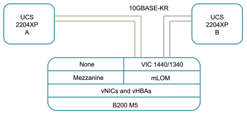
The connectivity between the UCS B200 blade servers and the IOMs are provided by the UCS VIC card through the UCS 5108 chassis backplane connections. The UCS 2204XP Fabric Extenders used for the validation has sixteen 10G ports each to connect to the eight half-width blade servers, for example, two for each server. To increase server connectivity bandwidth, an additional mezzanine-based VIC can be added to connect the server to the alternative UCS 2408 IOM which provides four 10G connections to each server.
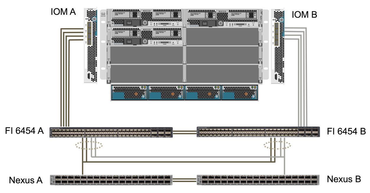
The connectivity between the UCS 5108 chassis and the UCS 6454 FIs used for the validation are provided by the IOM 2204XP which use four 10G connections. The FI ports 1 through 4 are configured as server ports for these connections. The FI ports 25 through 28 are configured as network uplink ports to the Nexus switch A and B at the local site. The following figure and table provide the connectivity diagram and port connection details for the UCS 6454 FIs to connect to the UCS 5108 chassis and the Nexus switches.
| Local device | Local port | Remote device | Remote port |
|---|---|---|---|
UCS 6454 FI A |
1 |
IOM A |
1 |
2 |
2 |
||
3 |
3 |
||
4 |
4 |
||
25 |
Nexus A |
1/13/1 |
|
26 |
1/13/2 |
||
27 |
Nexus B |
1/13/3 |
|
28 |
1/13/4 |
||
L1 |
UCS 6454 FI B |
L1 |
|
L2 |
L2 |
||
UCS 6454 FI B |
1 |
IOM B |
1 |
2 |
2 |
||
3 |
3 |
||
4 |
4 |
||
25 |
Nexus A |
1/13/3 |
|
26 |
1/13/4 |
||
27 |
Nexus B |
1/13/1 |
|
28 |
1/13/2 |
||
L1 |
UCS 6454 FI A |
L1 |
|
L2 |
L2 |

|
The connections above are similar for both sites A and B, despite site A using Nexus 9336C-FX2switches and site B using Nexus 3232C switches. 40G to 4x10G breakout cables are used for the Nexus to FI connections. The FI connections to Nexus utilizes port channel and virtual port channels are configured on the Nexus switches to aggregate the connections to each FI. |
|
|
When using a different combination of IOM, FI, and Nexus switch components, be sure to use appropriate cables and port speed for the environment combination. |
|
|
Additional bandwidth can be achieved by using components that support higher speed connections or more connections. Additional redundancy can be achieved by adding additional connections with components that support them. |
Service profiles
A blade server chassis with fabric interconnects managed by UCS Manager (UCSM) or Cisco Intersight can abstract the servers by using service profiles available in UCSM and server profiles in Intersight. This validation uses UCSM and service profiles to simplify server management. With service profiles, replacing or upgrading a server can be done simply by associating the original service profile with the new hardware.
The created service profiles support the following for the VMware ESXi hosts:
-
SAN boot from the AFF A250 storage at either site using iSCSI protocol.
-
Six vNICs are created for the servers where:
-
Two redundant vNICs (vSwitch0-A and vSwitch0-B) carry in-band management traffic. Optionally, these vNICs can also be used by NFS protocol data that is not protected by SM-BC.
-
Two redundant vNICs (vDS-A and vDS-B) are used by the vSphere distributed switch to carry VMware vMotion and other application traffic.
-
iSCSI-A vNIC used by iSCSI-A vSwitch to provide access to iSCSI-A path.
-
iSCSI-B vNIC used by iSCSI-B vSwitch to provide access to iSCSI-B path.
-
SAN boot
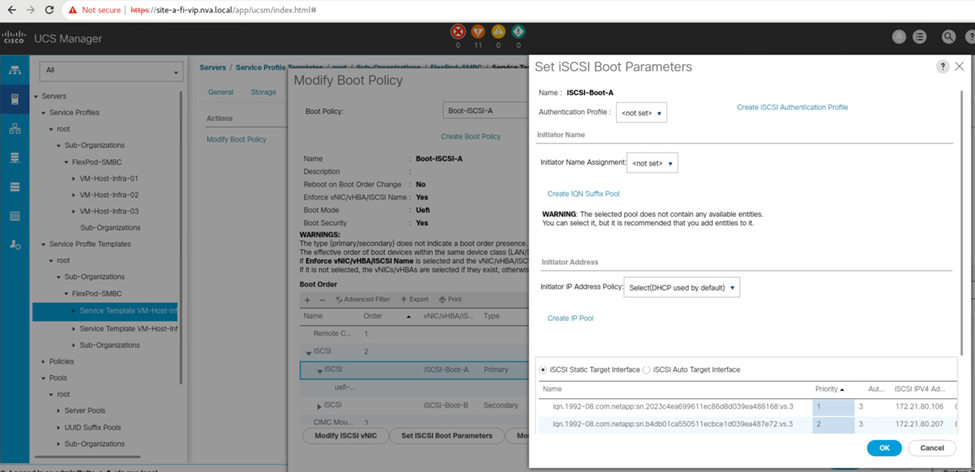
For iSCSI SAN boot configuration, the iSCSI boot parameters are set to allow iSCSI boot from both iSCSI fabrics. To accommodate the SM-BC failover scenario in which an iSCSI SAN boot LUN is served from the secondary cluster when the primary cluster is not available, the iSCSI static target configuration should include targets from both site A and site B. In addition, to maximize boot LUN availability, configure the iSCSI boot parameter settings to boot from all storage controllers.
The iSCSI static target can be configured in the boot policy of service profile templates under the Set iSCSI Boot Parameter dialog as shown in the following figure. The recommended iSCSI boot parameter setting configuration is shown in the following table, which implements the boot strategy discussed above to achieve high availability.
| iSCSI fabric | Priority | iSCSI target | iSCSI LIF |
|---|---|---|---|
iSCSI A |
1 |
Site A iSCSI target |
Site A Controller 1 iSCSI A LIF |
2 |
Site B iSCSI target |
Site B Controller 2 iSCSI A LIF |
|
iSCSI B |
1 |
Site B iSCSI target |
Site B Controller 1 iSCSI B LIF |
2 |
Site A iSCSI target |
Site A Controller 2 iSCSI B LIF |