

Solution validation - Network
 Suggest changes
The network configuration for FlexPod SM-BC solution follows typical FlexPod solution best practices at each site. For inter-site connectivity, the solution validation configuration connects the FlexPod Nexus switches at the two sites together to provide inter-site connectivity that extends VLANs between the two sites. The following sections highlight some of the connectivity and configurations used for the validation.
Connectivity
The FlexPod Nexus switches at each site provides the local connectivity between the UCS compute and ONTAP storage in a highly available configuration. The redundant components and redundant connectivity provide the resiliency against single-point-of-failure scenarios.
The following diagram shows the Nexus switch local connectivity at each site. In addition to what is shown in the diagram, there are also console and management network connections for each component that are not shown. The 40G to 4 x 10G breakout cables are used to connect the Nexus switches to the UCS FIs and the ONTAP AFF A250 storage controllers. Alternatively, the 100G to 4 x 25G breakout cables can be used to increase the communication speed between the Nexus switches and the AFF A250 storage controllers. For simplicity, the two AFF A250 controllers are logically shown as side-by-side for cabling illustration. The two connections between the two storage controllers allow the storage to form a switchless cluster.
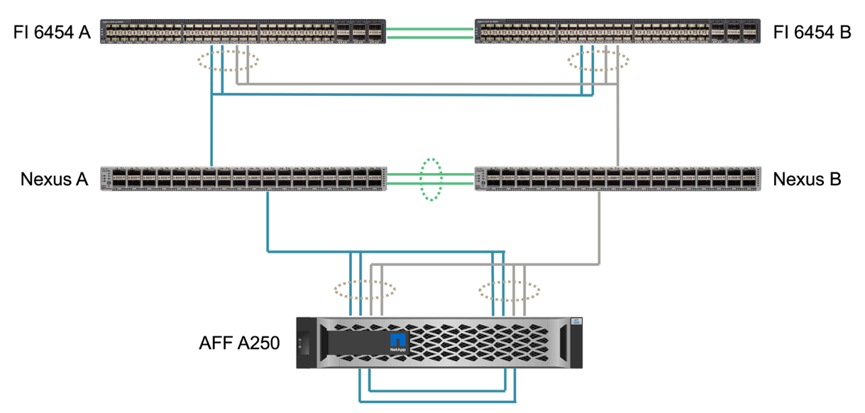
The following table shows the connectivity between Nexus switches and AFF A250 storage controllers at each site.
| Local device | Local port | Remote device | Remote port |
|---|---|---|---|
Nexus A |
1/10/1 |
AFF A250 A |
e1a |
1/10/2 |
e1b |
||
1/10/3 |
AFF A250 B |
e1a |
|
1/10/4 |
e1b |
||
Nexus B |
1/10/1 |
AFF A250 A |
e1c |
1/10/2 |
e1d |
||
1/10/3 |
AFF A250 B |
e1c |
|
1/10/4 |
e1d |
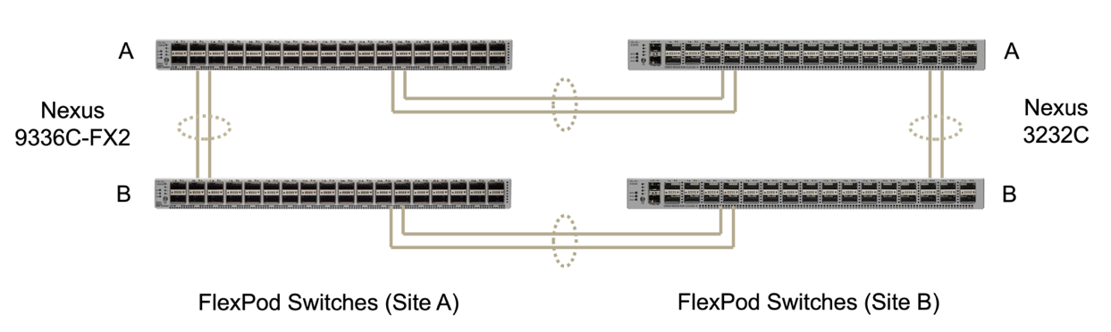
The connectivity between the FlexPod switches at site A and site B is shown in the following figure with cabling details listed in the accompanying table. The connections between the two switches at each site are for the vPC peer links. On the other hand, the connections between the switches across sites provide the inter-site links. The links extend the VLANs across sites for intercluster communication, SM-BC data replication, in-band management, and data access for the remote site resources.
| Local device | Local port | Remote device | Remote port |
|---|---|---|---|
Site A switch A |
33 |
Site B switch A |
31 |
34 |
32 |
||
25 |
Site A switch B |
25 |
|
26 |
26 |
||
Site A switch B |
33 |
Site B switch B |
31 |
34 |
32 |
||
25 |
Site A switch A |
25 |
|
26 |
26 |
||
Site B switch A |
31 |
Site A switch A |
33 |
32 |
34 |
||
25 |
Site B switch B |
25 |
|
26 |
26 |
||
Site B switch B |
31 |
Site A switch B |
33 |
32 |
34 |
||
25 |
Site B switch A |
25 |
|
26 |
26 |

|
The table above lists connectivity from the perspectives of each FlexPod switch. As a result, the table contains duplicate information for readability. |
Port channel and virtual port channel
Port channel enables link aggregation by using the Link Aggregation Control Protocol (LACP) for bandwidth aggregation and link failure resiliency. Virtual port channel (vPC) allows the port channel connections between two Nexus switches to logically appear as one. This further improves failure resiliency for scenarios such as a single link failure or a single switch failure.
The UCS server traffic to storage take the paths of IOM A to FI A and IOM B to FI B before reaching the Nexus switches. As the FI connections to Nexus switches utilize port channel on the FI side and virtual port channel on the Nexus switch side, the UCS server can effectively use paths through both Nexus switches and can survive single-point-of-failure scenarios. Between the two sites, the Nexus switches are inter-connected as illustrated in the previous figure. There are two links each to connect the switch pairs between the sites and they also use a port- channel configuration.
The in-band management, inter-cluster, and iSCSI / NFS data storage protocol connectivity is provided by interconnecting the storage controllers at each site to the local Nexus switches in a redundant configuration. Each storage controller is connected to two Nexus switches. The four connections are configured as part of an interface group on the storage for increased resiliency. On the Nexus switch side, those ports are also part of a vPC between switches.
The following table lists the port channel ID and usage at each site.
| Port channel ID | Usage |
|---|---|
10 |
Local Nexus peer link |
15 |
Fabric interconnect A links |
16 |
Fabric interconnect B links |
27 |
Storage controller A links |
28 |
Storage controller B links |
100 |
Inter-site switch A links |
200 |
Inter-site switch B links |
VLANs
The following table lists VLANs configured for setting up the FlexPod SM-BC solution validation environment along with their usage.
| Name | VLAN ID | Usage |
|---|---|---|
Native-VLAN |
2 |
VLAN 2 used as native VLAN instead of default VLAN (1) |
OOB-MGMT-VLAN |
3333 |
Out-of-band management VLAN for devices |
IB-MGMT-VLAN |
3334 |
In-band management VLAN for ESXi hosts, VM management, etc. |
NFS-VLAN |
3335 |
Optional NFS VLAN for NFS traffic |
iSCSI-A-VLAN |
3336 |
iSCSI-A fabric VLAN for iSCSI traffic |
iSCSI-B-VLAN |
3337 |
iSCSI-B fabric VLAN for iSCSI traffic |
vMotion-VLAN |
3338 |
VMware vMotion traffic VLAN |
VM-Traffic-VLAN |
3339 |
VMware VM traffic VLAN |
Intercluster-VLAN |
3340 |
Intercluster VLAN for ONTAP cluster peer communications |
|
|
While SM-BC does not support NFS or CIFS protocols for business continuity, you can still use them for workloads that do not need to be protected for business continuity. NFS datastores were not created for this validation. |