

FlexPod SM-BC solution
 Suggest changes
Solution overview
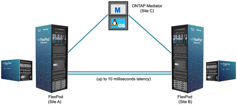
At a high level, a FlexPod SM-BC solution consists of two FlexPod systems, located at two sites separated by some distance, connected, and paired together to provide a highly available, highly flexible, and highly reliable data center solution that can provide business continuity despite a site failure.
In addition to deploying two new FlexPod infrastructures to create a FlexPod SM-BC solution, the solution can also be implemented on two existing FlexPod infrastructures that are compatible with SM-BC or by adding a new FlexPod to peer with an existing FlexPod.
The two FlexPod systems in a FlexPod SM-BC solution do not need to be identical in configurations. However, the two ONTAP clusters need to be of the same storage families, either two AFF or two ASA systems, but not necessarily the same hardware model. The SM-BC solution does not support FAS systems.
The two FlexPod sites require network connectivity which meets the solution bandwidth and quality-of-service requirements and has less than 10 milliseconds (10ms) round-trip latency between sites as required by the ONTAP SM-BC solution. For this FlexPod SM-BC solution validation, the two FlexPod sites are interconnected via extended layer-2 network in the same lab.
The NetApp ONTAP SM-BC solution provides synchronous replication between the two NetApp storage clusters for high availability and disaster recovery in a campus or metropolitan area. The ONTAP Mediator deployed at a third site monitors the solution and enables automated failover in case of a site disaster. The following figure provides a high-level view of the solution components.
With the FlexPod SM-BC solution, you can deploy a VMware vSphere-based private cloud on a distributed and yet integrated infrastructure. The integrated solution enables multiple sites to be coordinated as a single solution infrastructure to protect data services from a variety of single-point-of-failure scenarios and a complete site failure.
This technical report highlights some of the end-to-end design considerations of the FlexPod SM-BC solution. The practitioners are encouraged to reference information available in the various FlexPod CVDs and NVAs for additional FlexPod solution implementation details.
Although the solution was validated by deploying two FlexPod systems based on FlexPod best practices as documented in CVDs, it takes into accounts the requirements for the SM-BC solution. The deployed FlexPod SM-BC solution discussed in this report has been validated for resiliency and fault tolerance during various failure scenarios as well as a simulated site failure scenario.
Solution requirements
The FlexPod SM-BC solution is designed to address the following key requirements:
-
Business continuity for business-critical applications and data services in the event of a complete data center (site) failure
-
Flexible, distributed workload placement with workload mobility across data centers
-
Site affinity where virtual machine data is accessed locally, from the same data center site, during normal operations
-
Quick recovery with zero data loss when a site failure occurs
Solution components
Cisco compute components
The Cisco UCS is an integrated computing infrastructure to provide unified computing resources, unified fabric, and unified management. It enables companies to automate and accelerate deployment of applications, including virtualization and bare-metal workloads. The Cisco UCS supports a wide range of deployment use cases including remote and branch locations, data centers, and hybrid cloud use cases. Depending on the specific solution requirements, the FlexPod Cisco compute implementation can utilize a variety of components at different scales. The following subsections provide additional information on some of the UCS components.
UCS server and compute node
The following figure shows some examples of the UCS server components, including UCS C- Series rack servers, UCS 5108 chassis with B-Series blade servers, and the new UCS X9508 chassis with X-Series compute nodes. The Cisco UCS C-Series rack servers are available in one and two rack-unit (RU) form factor, Intel and AMD CPU based models, and with various CPU speeds and cores, memory, and I/O options. The Cisco UCS B-Series blade servers and the new X-Series compute nodes are also available with various CPU, memory, and I/O options, and they are all supported in the FlexPod architecture to meet the diverse business requirements.
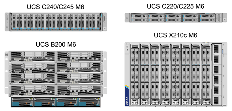
In addition to the latest generation C220/C225/C240/C245 M6 rack servers, B200 M6 blade servers, and X210c compute nodes shown in this figure, prior generations of rack and blade servers can also be used if they are still supported.
I/O Module and Intelligent Fabric Module
The I/O Module (IOM)/Fabric Extender and Intelligent Fabric Module (IFM) provide unified fabric connectivity for the Cisco UCS 5108 blade server chassis and the Cisco UCS X9508 X-Series chassis, respectively.
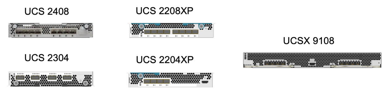
The fourth generation UCS IOM 2408 has eight 25-G unified Ethernet ports for connecting the UCS 5108 chassis with Fabric Interconnect (FI). Each 2408 has four 10-G backplane Ethernet connectivity through the midplane to each blade server in the chassis.
The UCSX 9108 25G IFM has eight 25-G unified Ethernet ports for connecting the blade servers in the UCS X9508 chassis with fabric interconnects. Each 9108 has four 25-G connections towards each UCS X210c compute node in the X9108 chassis. The 9108 IFM also works in concert with the fabric interconnect to manage the chassis environment.
The following figure depicts the UCS 2408 and earlier IOM generations for the UCS 5108 chassis and the 9108 IFM for the X9508 chassis.
UCS Fabric Interconnects
The Cisco UCS Fabric Interconnects (FIs) provide connectivity and management for the entire Cisco UCS. Typically deployed as an active/active pair, the system’s FIs integrate all components into a single, highly available management domain controlled by the Cisco UCS Manager or Cisco Intersight. Cisco UCS FIs provide a single unified fabric for the system with low-latency and lossless, cut-through switching that supports LAN, SAN, and management traffic using a single set of cables.
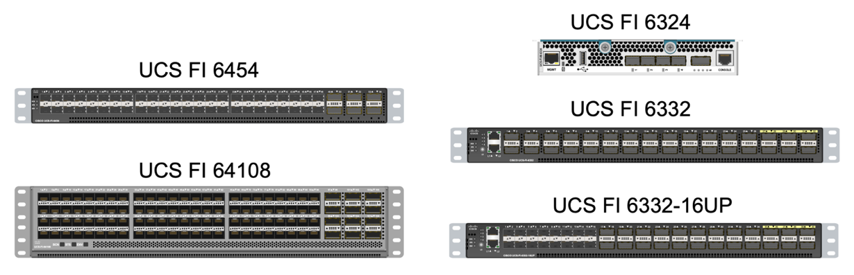
There are two variants for the fourth-generation Cisco UCS FIs: UCS FI 6454 and 64108. They include support for 10/25 Gbps Ethernet ports, 1/10/25-Gbps Ethernet ports, 40/100-Gbps Ethernet up-link ports, and unified ports that can support 10/25 Gigabit Ethernet or 8/16/32-Gbps Fibre Channel. The following figure shows the fourth-generation Cisco UCS FIs along with the third-generation models that are also supported.

|
To support the Cisco UCS X-Series chassis, fourth-generation fabric interconnects configured in Intersight Managed Mode (IMM) are required. However, the Cisco UCS 5108 B-series chassis can be supported both in IMM mode and in UCSM managed mode. |
|
|
The UCS FI 6324 uses the IOM form factor and is embedded in a UCS Mini chassis for deployments that require only a small UCS domain. |
UCS Virtual Interface Cards
Cisco UCS Virtual Interface Cards (VICs) unify system management and LAN and SAN connectivity for rack and blade servers. It supports up to 256 virtual devices, either as virtual Network Interface Cards (vNICs) or as virtual Host Bus Adapters (vHBAs) using the Cisco SingleConnect technology. As a result of virtualization, the VIC cards greatly simplify the network connectivity and reduce the number of network adapters, cables, and switch ports needed for solution deployment. The following figure shows some of the Cisco UCS VICs available for the B-Series and C-Series servers and the X-Series compute nodes.
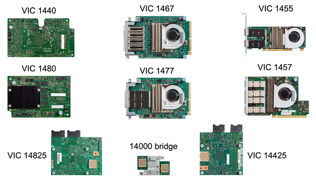
The different adapter models support different blade and rack servers with different port counts, port speeds, and form factors of modular LAN on Motherboard (mLOM), mezzanine cards, and PCIe interfaces. The adapters can support some combinations of 10/25/40/100-G Ethernet and Fibre Channel over Ethernet (FCoE). They incorporate Cisco’s Converged Network Adapter (CNA) technology, support a comprehensive feature set, and simplify adapter management and application deployment. For example, the VIC supports Cisco’s Data Center Virtual Machine Fabric Extender (VM-FEX) technology, which extends the Cisco UCS fabric interconnect ports to virtual machines, thus simplifying server virtualization deployment.
With a combination of Cisco VIC in mLOM, mezzanine, and port expander and bridge card configurations, you can take full advantage of the bandwidth and connectivity available to the blade servers. For example, by using the two 25-G links on the VIC 14825 (mLOM) and 14425 (mezzanine) and the 14000 (bridge card) for the X210c compute node, the combined VIC bandwidth is 2 x 50-G + 2 x 50-G, or 100G per fabric/IFM and 200G total per server with the dual IFM configuration.
For details on the Cisco UCS product families, technical specifications, and documentations, see the Cisco UCS web site for information.
Cisco switching components
Nexus switches
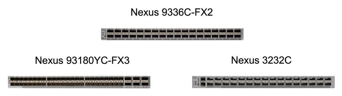
FlexPod uses Cisco Nexus Series switches to provide Ethernet switching fabric for communications between Cisco UCS and NetApp storage controllers. All currently supported Cisco Nexus switch models, including the Cisco Nexus 3000, 5000, 7000, and 9000 Series, are supported for FlexPod deployment.
When selecting a switch model for FlexPod deployment, there are many factors to consider, such as performance, port speed, port density, switching latency, and protocols such as ACI and VXLAN support, for your design objectives as well as the switches’ support timespan.
The validation for many recent FlexPod CVDs uses Cisco Nexus 9000 series switches such as the Nexus 9336C-FX2 and the Nexus 93180YC-FX3, which deliver high performance 40/100G and 10//25G ports, low latency, and exceptional power efficiency in a compact 1U form factor. Additional speeds are supported via uplink ports and breakout cables. The following figure shows a few Cisco Nexus 9k and 3k switches, including the Nexus 9336C-FX2 and the Nexus 3232C used for this validation.
See Cisco Data Center Switches for more information on the available Nexus switches and their specifications and documentations.
MDS switches
The Cisco MDS 9100/9200/9300 Series Fabric switches are an optional component in the FlexPod architecture. These switches are highly reliable, highly flexible, secure, and can provide visibility into the traffic flow in the fabric. The following figure shows some example MDS switches that can be used to build redundant FC SAN fabrics for a FlexPod solution to meet application and business requirements.
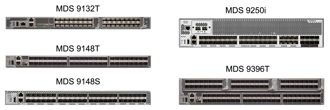
Cisco MDS 9132T/9148T/9396T high performance 32G Multilayer Fabric Switches are cost effective and are highly reliable, flexible, and scalable. The advanced storage networking features and functions come with ease of management and are compatible with the entire Cisco MDS 9000 family portfolio for a reliable SAN implementation.
State-of-the-art SAN analytics and telemetry capabilities are built into this next-generation hardware platform. The telemetry data extracted from the inspection of the frame headers can be streamed to an analytics-visualization platform, including the Cisco Data Center Network Manager. The MDS switches supporting 16G FC, such as the MDS 9148S, are also supported in FlexPod. In addition, Multiservice MDS switches, such as MDS 9250i, which supports FCoE and FCIP protocols in addition to FC protocol, are also part of the FlexPod solution portfolio.
On semi-modular MDS switches such as 9132T and 9396T, additional port expansion module and port licenses can be added to support additional device connectivity. On the fixed switches such as 9148T, additional port licenses can be added as needed. This pay-as-you-grow flexibility provides an operational expenses component to help reduce the capital expenses for the implementation and operation of MDS switch-based SAN infrastructure.
See Cisco MDS Fabric Switches for more information on the available MDS Fabric switches and see the NetApp IMT and Cisco Hardware and Software Compatibility List for a complete list of supported SAN switches.
NetApp components
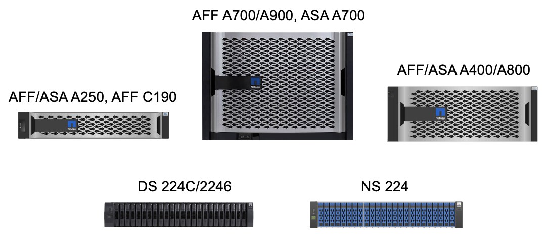
Redundant NetApp AFF or ASA controllers running ONTAP software 9.8, or later releases are required to create a FlexPod SM-BC solution. The latest ONTAP release, currently 9.10.1, is recommended for SM-BC deployment to take advantage of continued ONTAP innovations, performance, and quality improvements and the increased maximum object count for SM-BC support.
NetApp AFF and ASA controllers with industry-leading performance and innovations provide enterprise data protection and feature-rich data management capabilities. The AFF and ASA systems support end-to-end NVMe technologies, including NVMe-attached SSDs and NVMe over Fibre Channel (NVMe/FC) front-end host connectivity. You can improve your workload throughput and reduce I/O latency by adopting NVMe/FC-based SAN infrastructure. However, NVMe/FC-based datastores can currently only be used for workloads not protected by SM-BC, because SM-BC solution currently supports only iSCSI and FC protocols.
NetApp AFF and ASA storage controllers also provide a hybrid-cloud foundation for customers to take advantages of the seamless data mobility enabled by NetApp Data Fabric. With Data Fabric, you can easily get data from the edge where it is generated to the core where it is used and to the cloud to take advantage of the on-demand elastic compute and AI and ML capabilities to gain actionable business insights.
As shown in the following figure, NetApp offers a variety of storage controllers and disk shelves to meet your performance and capacity requirements. See the following table for links to product pages for information about the NetApp AFF and ASA controller capabilities and specifications.
| Product family | Technical specifications |
|---|---|
AFF series |
|
ASA series |
Consult the NetApp disk shelves and storage media documentation and NetApp Hardware Universe for details on the disk shelves and the supported disk shelves for each storage controller model.
Solution topologies
FlexPod solutions are flexible in topology and can be scaled up or scaled out to meet different solution requirements. A solution that requires business continuity protection and only minimum compute and storage resources can use a simple solution topology, as illustrated in the following figure. This simple topology uses the UCS C-Series rack servers and AFF/ASA controllers with SSDs in the controller without additional disk shelves.
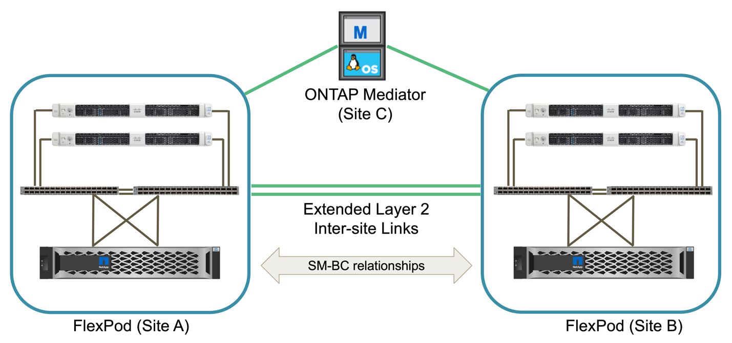
The redundant compute, network, and storage components are interconnected with redundant connectivity between the components. This highly available design provides solution resiliency and enables it to withstand single-point-of-failure scenarios. The multi-site design and ONTAP SM-BC synchronous data replication relationships provide business-critical data services despite the potential for single-site storage failure.
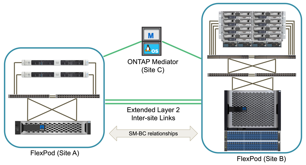
An asymmetric deployment topology that could be used by companies between a data center and a branch office in a metropolitan area might look like the following figure. For this asymmetric design, the data center requires a higher performance FlexPod with more compute and storage resources. However, the branch office requirement is less and can be met by a much smaller FlexPod.
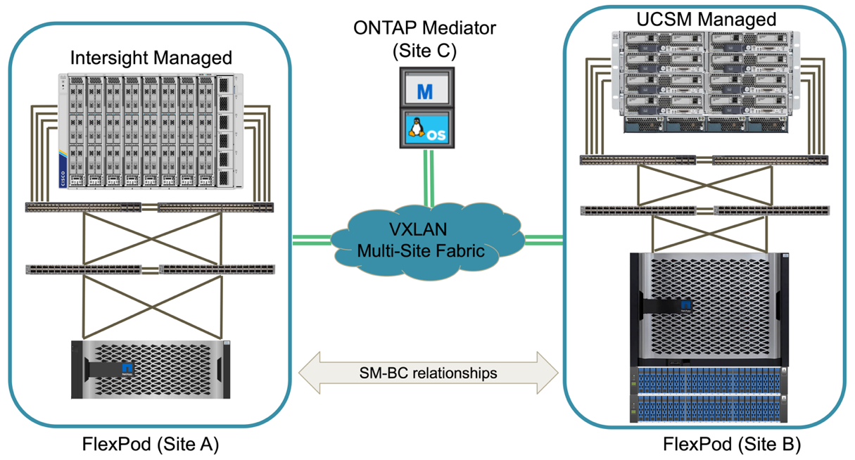
For companies with greater compute and storage resource requirements and multiple sites, a VXLAN-based multi-site fabric allows the multiple sites to have a seamless network fabric to facilitate application mobility so an application can be served from any site.
There might be an existing FlexPod solution using the Cisco UCS 5108 chassis and B-Series blade servers that must be protected by a new FlexPod instance. The new FlexPod instance can use the latest UCS X9508 chassis with X210c compute nodes managed by Cisco Intersight, as shown in the following figure. In this case, the FlexPod systems at each site are connected to a larger data center fabric, and the sites are connected through an interconnect network to form a VXLAN multi-site fabric.
For companies that have a datacenter and several branch offices in a metro area that all need to be protected to provide business continuity, the FlexPod SM-BC deployment topology shown in the following figure can be implemented to protect critical application and data services to achieve zero RPO and near zero RTO objectives for all branch sites.
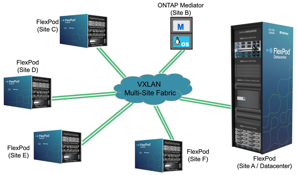
For this deployment model, each branch office establishes the SM-BC relationships and consistency groups it requires with the datacenter. You must take into account the supported SM-BC object limits, so the overall consistency group relationships and endpoint counts do not exceed the supported maximums at the datacenter.