

Deploy Cisco UCS C-Series rack server
 Suggest changes
This section provides a detailed procedure for configuring a Cisco UCS C-Series standalone rack server for use in the FlexPod Express configuration.
Perform the initial Cisco UCS C-Series standalone server setup for CIMC
Complete these steps for the initial setup of the CIMC interface for Cisco UCS C-Series standalone servers.
The following table lists the information needed to configure CIMC for each Cisco UCS C-Series standalone server.
| Detail | Detail value |
|---|---|
CIMC IP address |
<<cimc_ip>> |
CIMC subnet mask |
\<<cimc_netmask |
CIMC default gateway |
<<cimc_gateway>> |

|
The CIMC version used in this validation is CIMC 4.0.(4). |
All servers
-
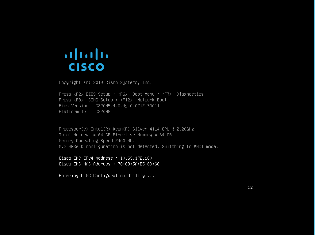
Attach the Cisco keyboard, video, and mouse (KVM) dongle (provided with the server) to the KVM port on the front of the server. Plug a VGA monitor and USB keyboard into the appropriate KVM dongle ports.
Power on the server and press F8 when prompted to enter the CIMC configuration.
-
In the CIMC configuration utility, set the following options:
-
Network interface card (NIC) mode:
Dedicated
[X] -
IP (Basic):
IPV4:
[X]DHCP enabled:
[ ]CIMC IP:
<<cimc_ip>>Prefix/Subnet:
<<cimc_netmask>>Gateway:
<<cimc_gateway>> -
VLAN (Advanced): Leave cleared to disable VLAN tagging.
NIC redundancy
None:
[X]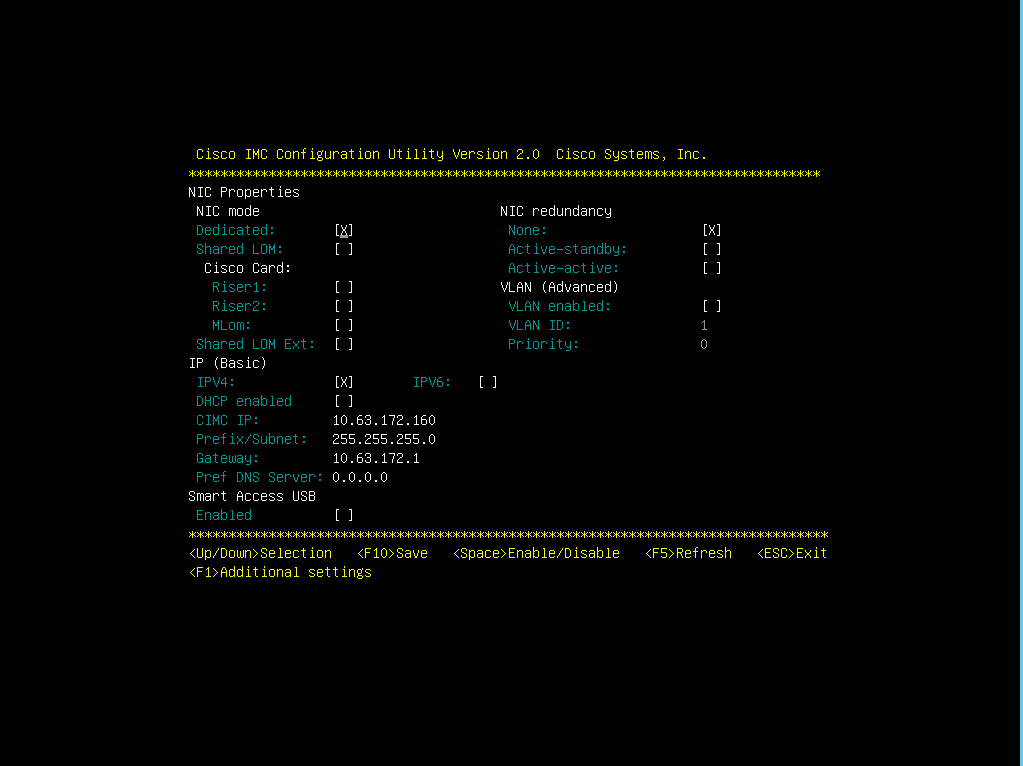
-
-
Press F1 to see the additional settings:
-
Common properties:
Host name:
<<esxi_host_name>>Dynamic DNS:
[ ]Factory defaults: Leave cleared.
-
Default user (basic):
Default password:
<<admin_password>>Reenter password:
<<admin_password>>Port properties: Use default values.
Port profiles: Leave cleared.
-
-
Press F10 to save the CIMC interface configuration.
-
After the configuration is saved, press Esc to exit.
Configure Cisco UCS C-Series Servers iSCSI boot
In this FlexPod Express configuration, the VIC1457 is used for iSCSI boot.
The following table lists the information needed to configure iSCSI boot.
|
|
An italicized font indicates variables that are unique for each ESXi host. |
| Detail | Detail value |
|---|---|
ESXi host initiator A name |
<<var_ucs_initiator_name_A>> |
ESXi host iSCSI-A IP |
<<var_esxi_host_iscsiA_ip>> |
ESXi host iSCSI-A network mask |
<<var_esxi_host_iscsiA_mask>> |
ESXi host iSCSI A default gateway |
<<var_esxi_host_iscsiA_gateway>> |
ESXi host initiator B name |
<<var_ucs_initiator_name_B>> |
ESXi host iSCSI-B IP |
<<var_esxi_host_iscsiB_ip>> |
ESXi host iSCSI-B network mask |
<<var_esxi_host_iscsiB_mask>> |
ESXi host iSCSI-B gateway |
<<var_esxi_host_iscsiB_gateway>> |
IP address iscsi_lif01a |
<<var_iscsi_lif01a>> |
IP address iscsi_lif02a |
<<var_iscsi_lif02a>> |
IP address iscsi_lif01b |
<<var_iscsi_lif01b>> |
IP address iscsi_lif02b |
<<var_iscsi_lif02b>> |
Infra_SVM IQN |
<<var_SVM_IQN>> |
Boot order configuration
To set the boot order configuration, complete the following steps:
-
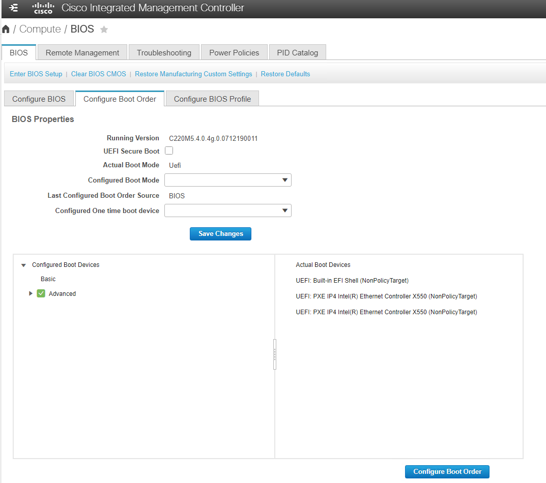
From the CIMC interface browser window, click the Compute tab and select BIOS.
-
Click Configure Boot Order and then click OK.
-
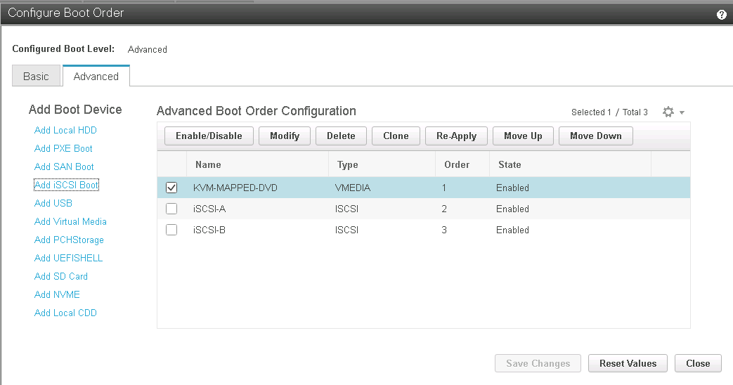
Configure the following devices by clicking the device under Add Boot Device and going to the Advanced tab:
-
Add Virtual Media:
Name: KVM-CD-DVD
Subtype: KVM MAPPED DVD
State: Enabled
Order: 1
-
Add iSCSI Boot:
Name: iSCSI-A
State: Enabled
Order: 2
Slot: MLOM
Port: 1
-
Click Add iSCSI Boot:
Name: iSCSI-B
State: Enabled
Order: 3
Slot: MLOM
Port: 3
-
-
Click Add Device.
-
Click Save Changes and then click Close.
-
Reboot the server to boot with your new boot order.
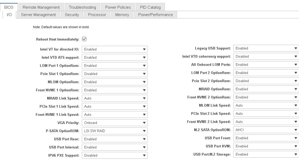
Disable RAID controller (if present)
Complete the following steps if your C-Series server contains a RAID controller. A RAID controller is not needed in the boot from SAN configuration. Optionally, you can also physically remove the RAID controller from the server.
-
Under the Compute tab, click BIOS in the left navigation pane in CIMC.
-
Select Configure BIOS.
-
Scroll down to PCIe Slot:HBA Option ROM.
-
If the value is not already disabled, set it to disabled.
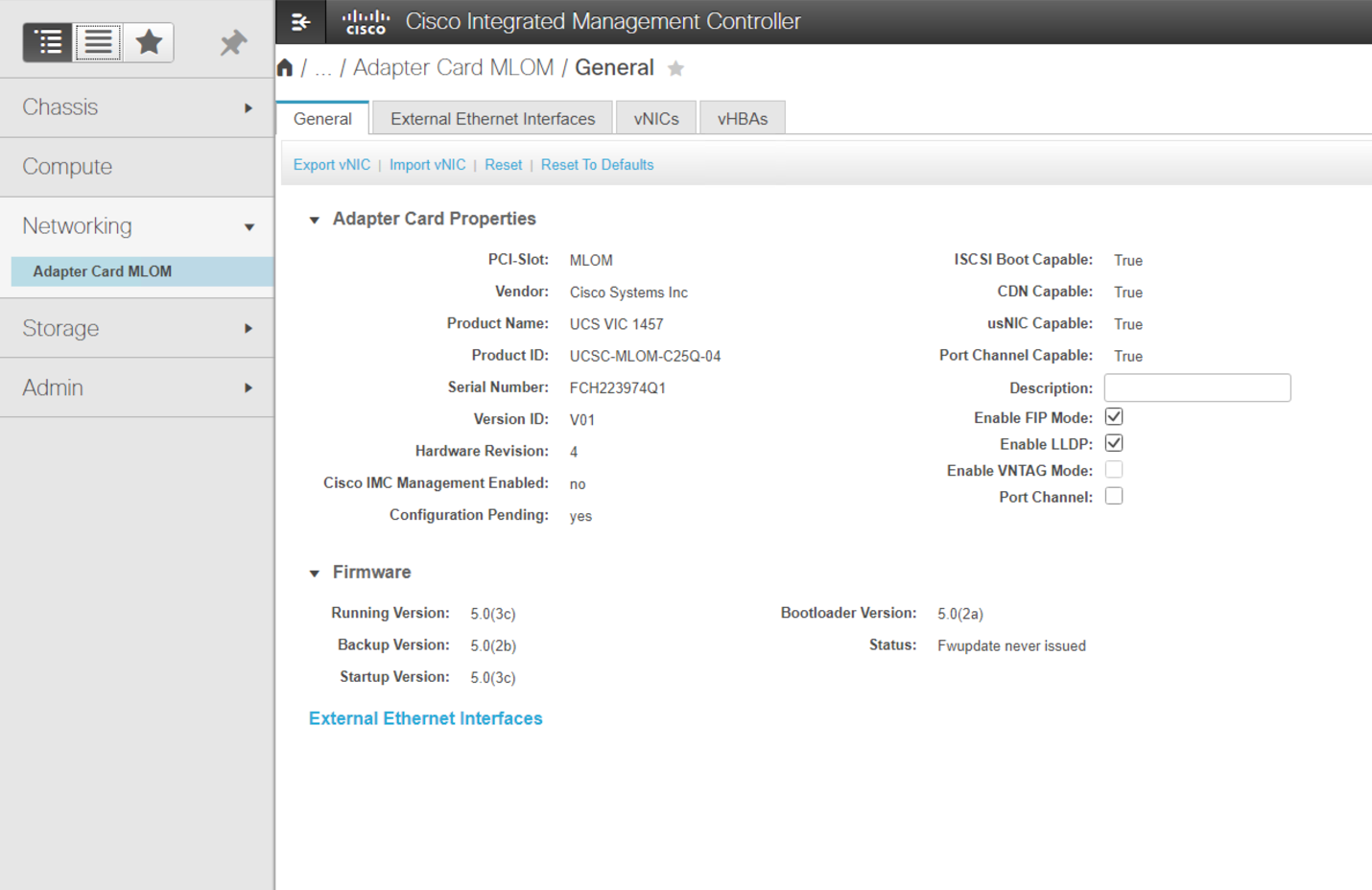
Configure Cisco VIC1457 for iSCSI boot
The following configuration steps are for the Cisco VIC 1457 for iSCSI boot.
|
|
The default port-channeling between ports 0, 1, 2, and 3 must be turned off before the four individual ports can be configured. If port channeling is not turned off, only two ports appear for the VIC 1457. Complete the following steps to enable the port channel on the CIMC: |
-
Under the networking tab, click the Adapter Card MLOM.
-
Under the General tab, uncheck the port channel.
-
Save the changes and reboot the CIMC.
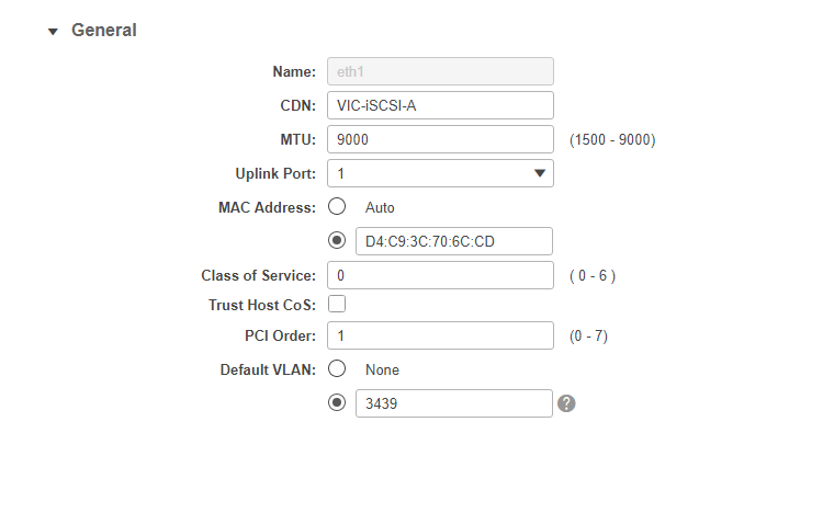
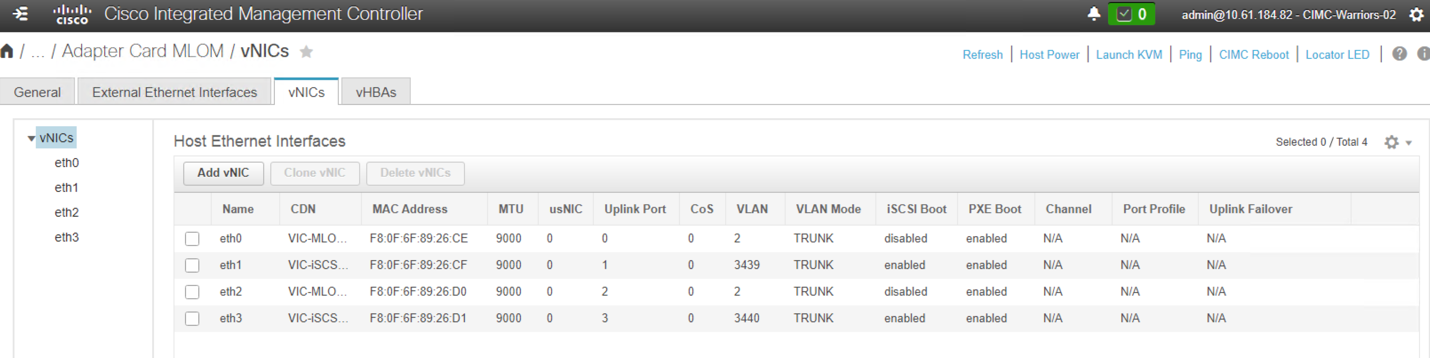
Create iSCSI vNICs
To create iSCSI vNICS, complete the following steps:
-
Under the networking tab, click Adapter Card MLOM.
-
Click Add vNIC to create a vNIC.
-
In the Add vNIC section, enter the following settings:
-
Name: eth1
-
CDN Name: iSCSI-vNIC-A
-
MTU: 9000
-
Default VLAN:
<<var_iscsi_vlan_a>> -
VLAN Mode: TRUNK
-
Enable PXE boot: Check
-
-
Click Add vNIC and then click OK.
-
Repeat the process to add a second vNIC:
-
Name the vNIC eth3.
-
CDN Name: iSCSI-vNIC-B
-
Enter
<<var_iscsi_vlan_b>>as the VLAN. -
Set the uplink port to 3.
-
-
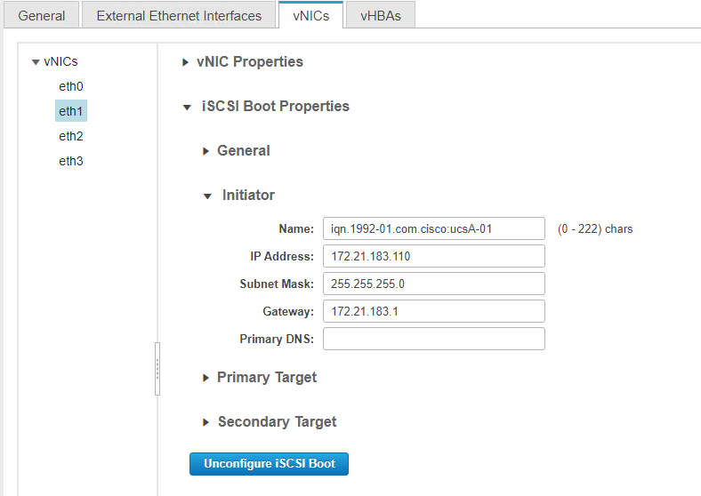
Select the vNIC eth1 on the left.
-
Under iSCSI Boot Properties, enter the initiator details:
-
Name:
<<var_ucsa_initiator_name_a>> -
IP address:
<<var_esxi_hostA_iscsiA_ip>> -
Subnet mask:
<<var_esxi_hostA_iscsiA_mask>> -
Gateway:
<<var_esxi_hostA_iscsiA_gateway>>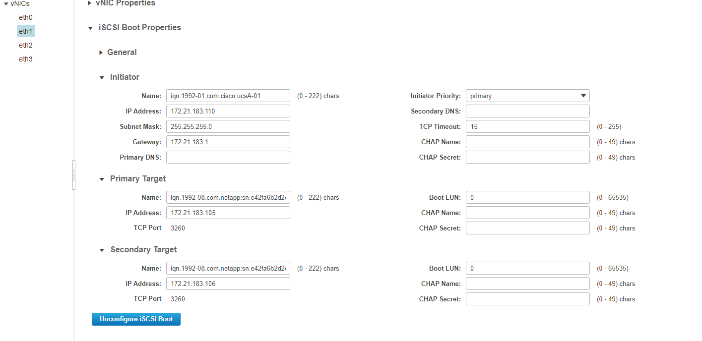
-
-
Enter the primary target details:
-
Name: IQN number of infra-SVM
-
IP address: IP address of iscsi_lif01a
-
Boot LUN: 0
-
-
Enter the secondary target details:
-
Name: IQN number of infra-SVM
-
IP address: IP address of iscsi_lif02a
-
Boot LUN:0
You can obtain the storage IQN number by running the vserver iscsi showcommand.
Be sure to record the IQN names for each vNIC. You need them for a later step. In addition, the IQN names for initiators must be unique for each server and for the iSCSI vNIC.
-
-
Click Save Changes.
-
Select the vNIC eth3 and click the iSCSI Boot button located on the top of the Host Ethernet Interfaces section.
-
Repeat the process to configure eth3.
-
Enter the initiator details:
-
Name:
<<var_ucsa_initiator_name_b>> -
IP address:
<<var_esxi_hostb_iscsib_ip>> -
Subnet mask:
<<var_esxi_hostb_iscsib_mask>> -
Gateway:
<<var_esxi_hostb_iscsib_gateway>>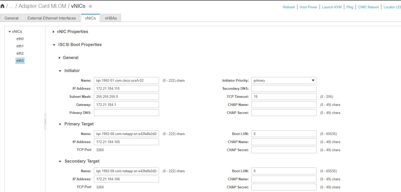
-
-
Enter the primary target details:
-
Name: IQN number of infra-SVM
-
IP address: IP address of iscsi_lif01b
-
Boot LUN: 0
-
-
Enter the secondary target details:
-
Name: IQN number of infra-SVM
-
IP address: IP address of iscsi_lif02b
-
Boot LUN: 0
You can obtain the storage IQN number by using the vserver iscsi showcommand.
Be sure to record the IQN names for each vNIC. You need them for a later step.
-
-
Click Save Changes.
-
Repeat this process to configure iSCSI boot for Cisco UCS server B.
Configure vNICs for ESXi
To configure vNICS for ESXi, complete the following steps:
-
From the CIMC interface browser window, click Inventory and then click Cisco VIC adapters on the right pane.
-
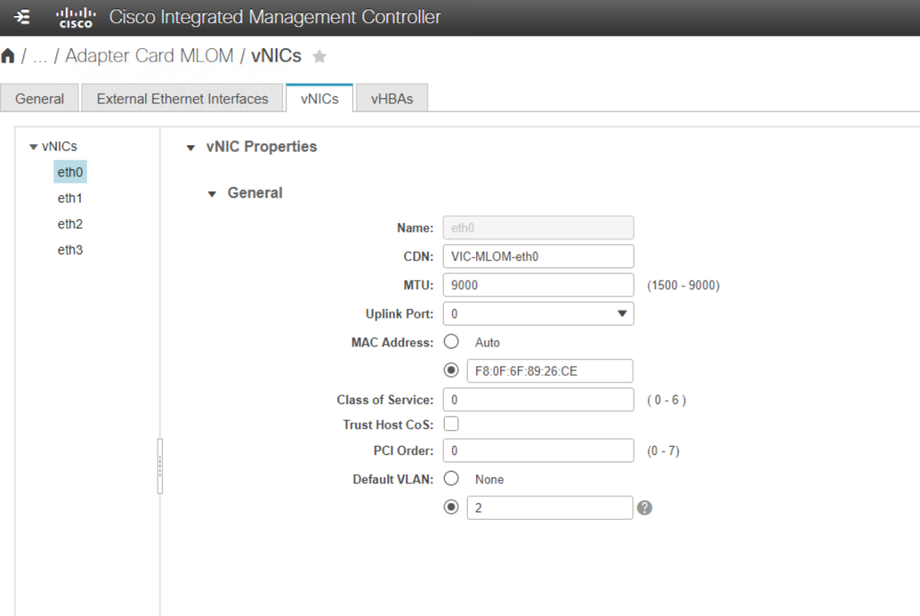
Under Networking > Adapter Card MLOM, select vNICs tab and then select the vNICs underneath.
-
Select eth0 and click Properties.
-
Set the MTU to 9000. Click Save Changes.
-
Set the VLAN to native VLAN 2.
-
Repeat steps 3 and 4 for eth1, verifying that the uplink port is set to 1 for eth1.
This procedure must be repeated for each initial Cisco UCS server node and each additional Cisco UCS server node added to the environment.