Solution validation - Storage
 Suggest changes
The storage configuration for FlexPod SM-BC solution follows typical FlexPod solution best practices at each site. For SM-BC cluster peering and data replication, they use the inter-site links established between the FlexPod switches at both sites. The following sections highlight some of the connectivity and configurations used for the validation.
Connectivity
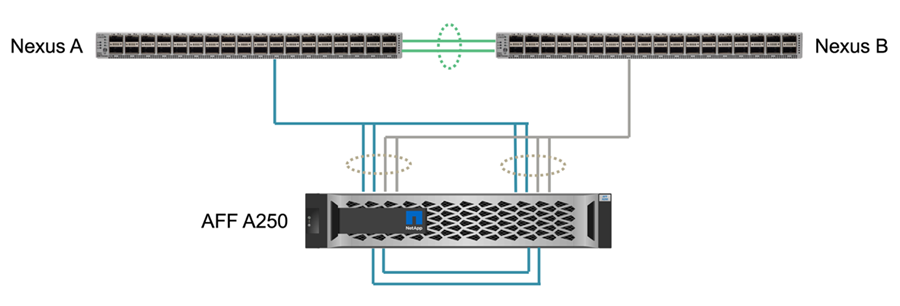
The storage connectivity to the local UCS FIs and blade servers is provided by the Nexus switches at the local site. Through the Nexus switch connectivity between sites, the storage can also be accessed by the remote UCS blade servers. The following figure and table show the storage connectivity diagram and a list of connections for the storage controllers at each site.
| Local device | Local port | Remote device | Remote port |
|---|---|---|---|
AFF A250 A |
e0c |
AFF A250 B |
e0c |
e0d |
e0d |
||
e1a |
Nexus A |
1/10/1 |
|
e1b |
1/10/2 |
||
e1c |
Nexus B |
1/10/1 |
|
e1d |
1/10/2 |
||
AFF A250 B |
e0c |
AFF A250 A |
e0c |
e0d |
e0d |
||
e1a |
Nexus A |
1/10/3 |
|
e1b |
1/10/4 |
||
e1c |
Nexus B |
1/10/3 |
|
e1d |
1/10/4 |
Connections and interfaces
Two physical ports on each storage controller are connected to each Nexus switches for bandwidth aggregation and redundancy for this validation. Those four connections participate in an interface group configuration on the storage. The corresponding ports on the Nexus switches participate in a vPC for link aggregation and resiliency.
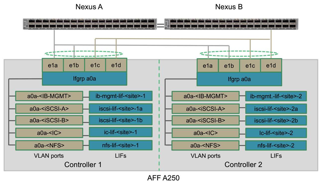
The in-band management, inter-cluster, and NFS/iSCSI data storage protocols use VLANs. VLAN ports are created on the interface group to segregate the different types of traffic. Logical interfaces (LIFs) for the respective functions are created on top of the corresponding VLAN ports. The following figure shows the relationship between the physical connections, interface groups, VLAN ports, and logical interfaces.
SAN boot
NetApp recommends implementing SAN boot for the Cisco UCS servers in the FlexPod solution. Implementing SAN boot enables you to safely secure the operating system within the NetApp storage system, providing better performance and flexibility. For this solution, iSCSI SAN boot was validated.
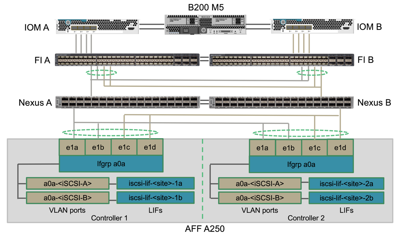
The following figure depicts the connectivity for iSCSI SAN boot of Cisco UCS server from NetApp Storage. In iSCSI SAN boot, each Cisco UCS server is assigned two iSCSI vNICs (one for each SAN fabric) that provide redundant connectivity from the server all the way to the storage. The 10/25-G Ethernet storage ports that are connected to the Nexus switches (in this example e1a, e1b, e1c, and e1d) are grouped together to form one interface group (ifgrp) (in this example, a0a). The iSCSI VLAN ports are created on the ifgrp and the iSCSI LIFs are created on the iSCSI VLAN ports.
Each iSCSI boot LUN is mapped to the server that boots from it through the iSCSI LIFs by associating the boot LUN with the server’s iSCSI Qualified Names (IQNs) in its boot igroup. The server’s boot igroup contains two IQNs, one for each vNIC / SAN fabric. This feature enables only the authorized server to have access to the boot LUN created specifically for that server.
Cluster peering
ONTAP cluster peers communicate via the intercluster LIFs. Using ONTAP System Manager for the two clusters, you can create the needed intercluster LIFs under the Protection > Overview pane.
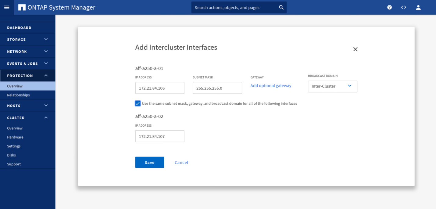
To peer the two clusters together, complete the following steps:
-
Generate cluster peering passphrase in the first cluster.
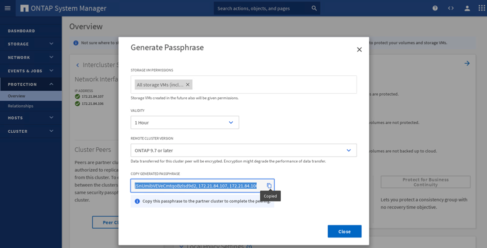
-
Invoke the Peer Cluster option in the second cluster and provide the passphrase and intercluster LIF information.
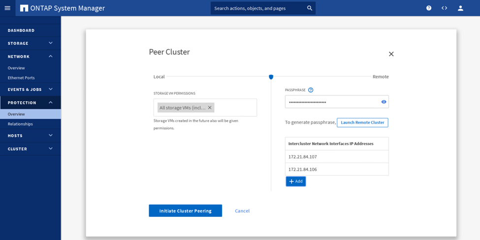
-
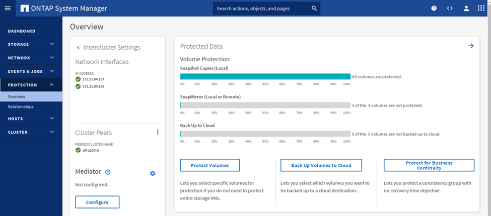
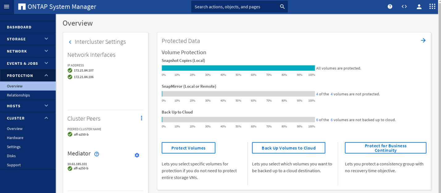
The System Manager Protection > Overview pane shows cluster peer information.
ONTAP Mediator installation and configuration
The ONTAP Mediator establishes a quorum for the ONTAP clusters in an SM-BC relationship. It coordinates automated failover when a failure is detected and helps to avoids split-brain scenarios when each cluster simultaneously tries to establish control as the primary cluster.
Before installing the ONTAP Mediator, check out the Install or upgrade the ONTAP Mediator service page for prerequisites, supported Linux versions, and the procedures for installing them on the various supported Linux operating systems.
After the ONTAP Mediator is installed, you can add the security certificate of the ONTAP Mediator to the ONTAP clusters and then configuring the ONTAP Mediator in the System Manager Protection > Overview pane. The following screenshot shows of the ONTAP Mediator configuration GUI.
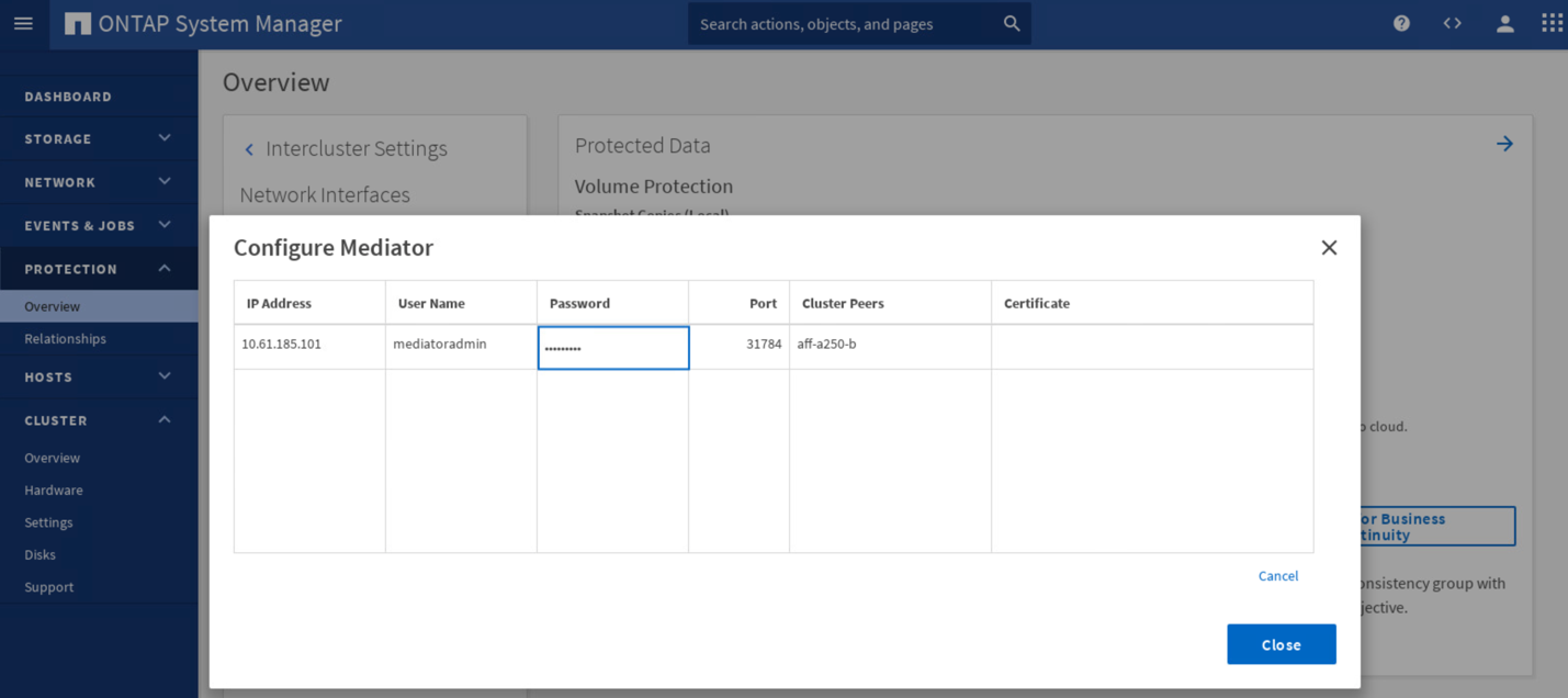
After you provide the necessary information, the configured ONTAP Mediator then appears in the System Manager Protection > Overview pane.
SM-BC consistency group
A consistency group provides a write-order consistency guarantee for an application workload spanning a collection of specified volumes. For ONTAP 9.10.1, here are some of the important restrictions and limitations.
-
The maximum number of SM-BC consistency group relationships in a cluster is 20.
-
The maximum number of volumes supported per SM-BC relationship is 16.
-
The maximum number of total source and destination endpoints in a cluster is 200.
For additional details, see the ONTAP SM-BC documentation on the restrictions and limitations.
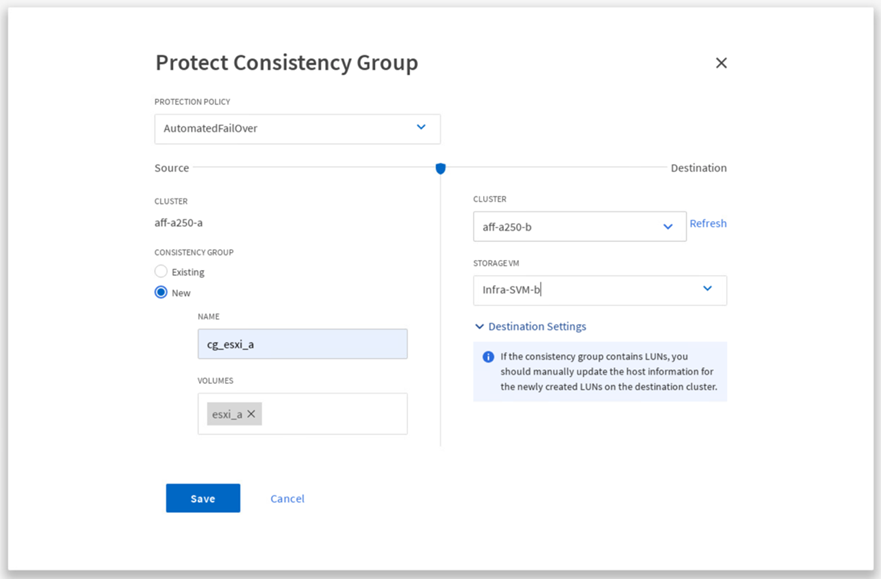
For the validation configuration, ONTAP System Manager was used to create the consistency groups to protect both the ESXi boot LUNs and the shared datastore LUNs for both sites. The consistency group creation dialog is accessible by going to Protection > Overview > Protect for Business Continuity > Protect Consistency Group. To create a consistency group, provide the needed source volumes, destination cluster, and destination storage virtual machine information for the creation.
The following table lists the four consistency groups that are created and the volumes that are included in each consistency group for the validation testing.
| System Manager | Consistency group | Volumes |
|---|---|---|
Site A |
cg_esxi_a |
esxi_a |
Site A |
cg_infra_datastore_a |
infra_datastore_a_01 |
Site B |
cg_esxi_b |
esxi_b |
Site B |
cg_infra_datastore_b |
infra_datastore_b_01 |
After the consistency groups are created, they show up under the respective protection relationships in site A and site B.
This screenshot shows the consistency group relationships at site A.
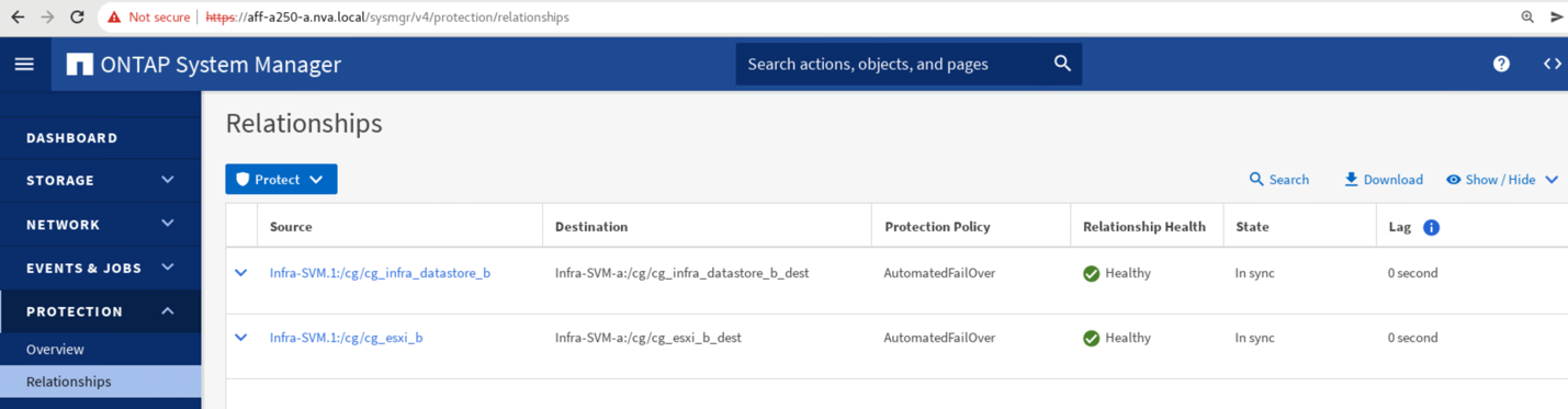
This screenshot shows the consistency group relationships at site B.

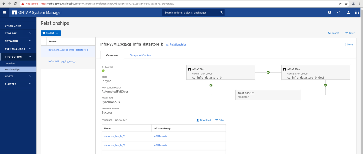
This screenshot shows the consistency group relationship details for the cg_infra_datastore_b group.
Volumes, LUNs, and host mappings
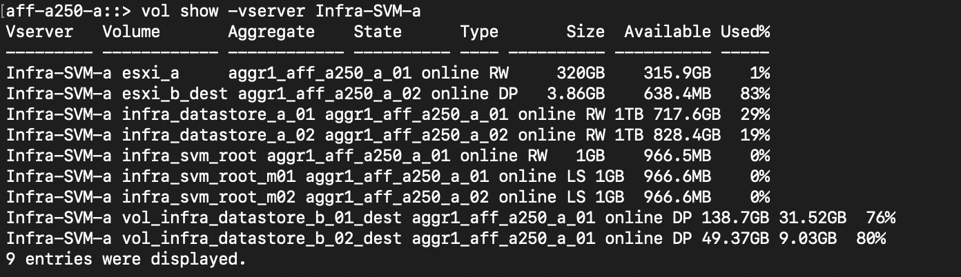
After the consistency groups are created, SnapMirror synchronizes the source and the destination volumes so the data can always be in sync. The destination volumes at the remote site carries the volume names with the _dest ending. For example, for the esxi_a volume in site A cluster, there is a corresponding esxi_a_dest data protection (DP) volume in site B.
This screenshot shows the volume information for site A.
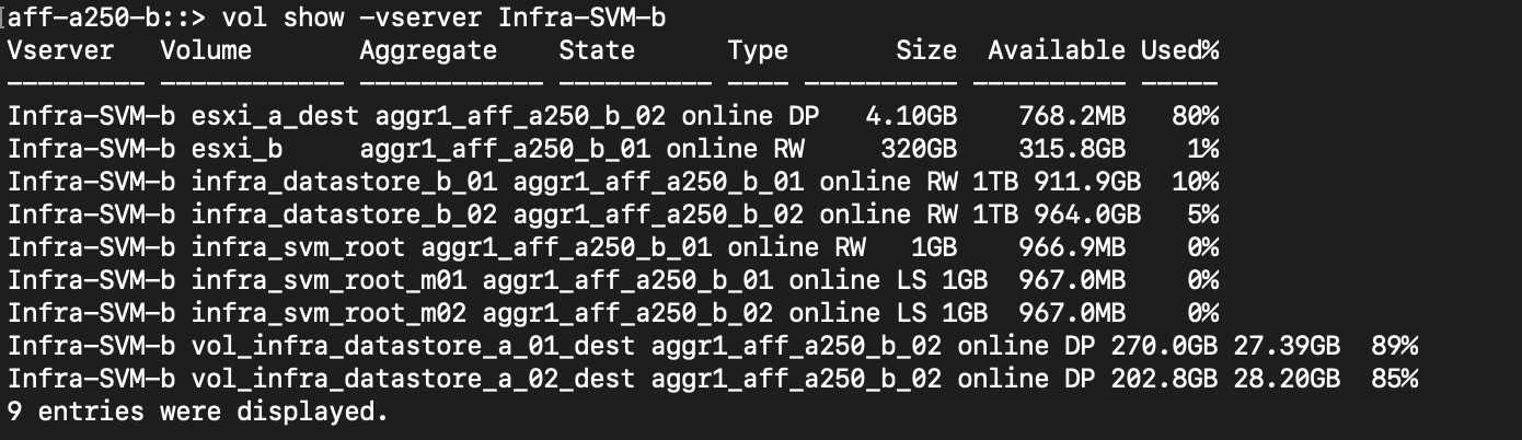
This screenshot shows the volume information for site B.
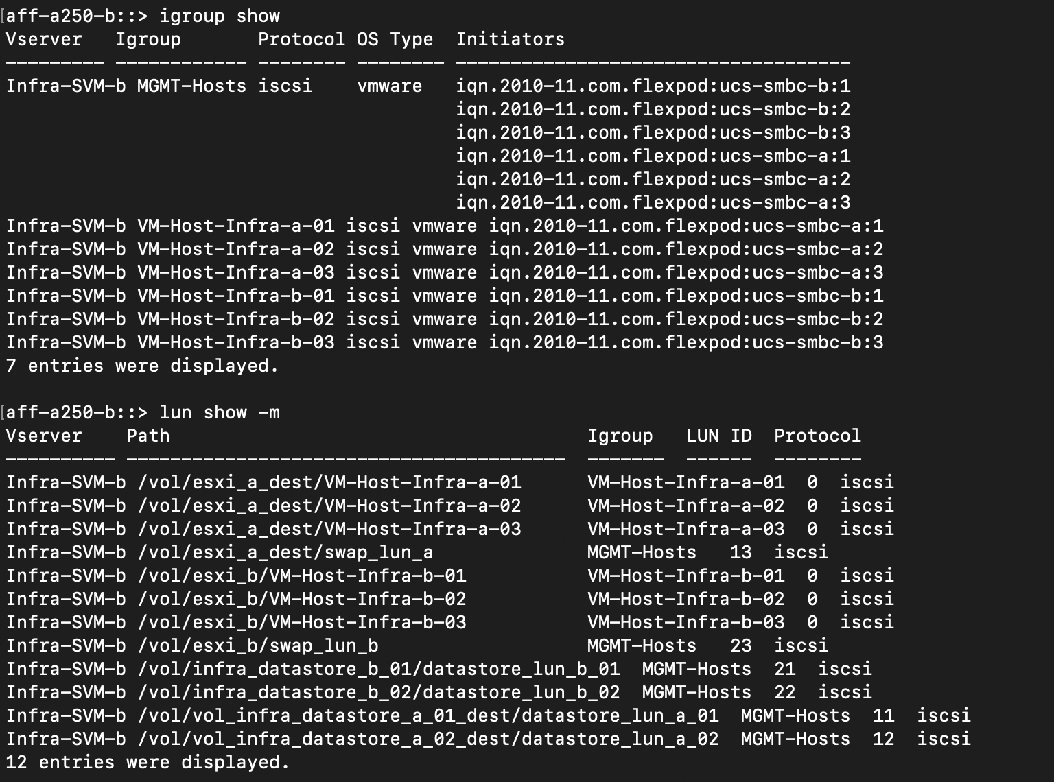
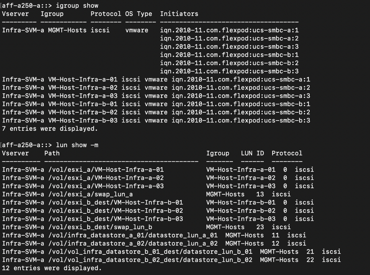
To facilitate transparent application failover, the mirrored SM-BC LUNs also need to be mapped to the hosts from the destination cluster. This allows the hosts to properly see paths to the LUNs from both the source and destination clusters. The igroup show and lun show outputs for both site A and site B are captured in the following two screenshots. With the created mappings, each ESXi host in the cluster sees its own SAN boot LUN as ID 0 and all the four shared iSCSI datastore LUNs.
This screenshot shows the host igroups and LUN mapping for site A cluster.
This screenshot shows the host igroups and LUN mapping for site B cluster.