Configure the host network (Red Hat Enterprise Linux or CentOS)
 Suggest changes


After completing the Linux installation on your hosts, you might need to perform some additional configuration to prepare a set of network interfaces on each host that are suitable for mapping into the StorageGRID nodes you will deploy later.
-
You have reviewed the StorageGRID networking guidelines.
-
You have reviewed the information about node container migration requirements.
-
If you are using virtual hosts, you have read the considerations and recommendations for MAC address cloning before configuring the host network.

|
If you are using VMs as hosts, you should select VMXNET 3 as the virtual network adapter. The VMware E1000 network adapter has caused connectivity issues with StorageGRID containers deployed on certain distributions of Linux. |
Grid nodes must be able to access the Grid Network and, optionally, the Admin and Client Networks. You provide this access by creating mappings that associate the host's physical interface to the virtual interfaces for each grid node. When creating host interfaces, use friendly names to facilitate deployment across all hosts, and to enable migration.
The same interface can be shared between the host and one or more nodes. For example, you might use the same interface for host access and node Admin Network access, to facilitate host and node maintenance. Although the same interface can be shared between the host and individual nodes, all must have different IP addresses. IP addresses can't be shared between nodes or between the host and any node.
You can use the same host network interface to provide the Grid Network interface for all StorageGRID nodes on the host; you can use a different host network interface for each node; or you can do something in between. However, you would not typically provide the same host network interface as both the Grid and Admin Network interfaces for a single node, or as the Grid Network interface for one node and the Client Network interface for another.
You can complete this task in many ways. For example, if your hosts are virtual machines and you are deploying one or two StorageGRID nodes for each host, you can create the correct number of network interfaces in the hypervisor, and use a 1-to-1 mapping. If you are deploying multiple nodes on bare metal hosts for production use, you can leverage the Linux networking stack's support for VLAN and LACP for fault tolerance and bandwidth sharing. The following sections provide detailed approaches for both of these examples. You don't need to use either of these examples; you can use any approach that meets your needs.

|
Don't use bond or bridge devices directly as the container network interface. Doing so could prevent node start-up caused by a kernel issue with the use of MACVLAN with bond and bridge devices in the container namespace. Instead, use a non-bond device, such as a VLAN or virtual Ethernet (veth) pair. Specify this device as the network interface in the node configuration file. |
Considerations and recommendations for MAC address cloning
MAC address cloning causes the container to use the MAC address of the host, and the host to use the MAC address of either an address you specify or a randomly generated one. You should use MAC address cloning to avoid the use of promiscuous mode network configurations.
Enabling MAC cloning
In certain environments, security can be enhanced through MAC address cloning because it enables you to use a dedicated virtual NIC for the Admin Network, Grid Network, and Client Network. Having the container use the MAC address of the dedicated NIC on the host allows you to avoid using promiscuous mode network configurations.

|
MAC address cloning is intended to be used with virtual server installations and might not function properly with all physical appliance configurations. |

|
If a node fails to start due to a MAC cloning targeted interface being busy, you might need to set the link to "down" before starting node. Additionally, it is possible that the virtual environment might prevent MAC cloning on a network interface while the link is up. If a node fails to set the MAC address and start due to an interface being busy, setting the link to "down" before starting the node might fix the issue. |
MAC address cloning is disabled by default and must be set by node configuration keys. You should enable it when you install StorageGRID.
There is one key for each network:
-
ADMIN_NETWORK_TARGET_TYPE_INTERFACE_CLONE_MAC -
GRID_NETWORK_TARGET_TYPE_INTERFACE_CLONE_MAC -
CLIENT_NETWORK_TARGET_TYPE_INTERFACE_CLONE_MAC
Setting the key to "true" causes the container to use the MAC address of the host's NIC. Additionally, the host will then use the MAC address of the specified container network. By default, the container address is a randomly generated address, but if you have set one using the _NETWORK_MAC node configuration key, that address is used instead. The host and container will always have different MAC addresses.

|
Enabling MAC cloning on a virtual host without also enabling promiscuous mode on the hypervisor might cause Linux host networking using the host's interface to stop working. |
MAC cloning use cases
There are two use cases to consider with MAC cloning:
-
MAC cloning not enabled: When the
_CLONE_MACkey in the node configuration file is not set, or set to "false," the host will use the host NIC MAC and the container will have a StorageGRID-generated MAC unless a MAC is specified in the_NETWORK_MACkey. If an address is set in the_NETWORK_MACkey, the container will have the address specified in the_NETWORK_MACkey. This configuration of keys requires the use of promiscuous mode. -
MAC cloning enabled: When the
_CLONE_MACkey in the node configuration file is set to "true," the container uses the host NIC MAC, and the host uses a StorageGRID-generated MAC unless a MAC is specified in the_NETWORK_MACkey. If an address is set in the_NETWORK_MACkey, the host uses the specified address instead of a generated one. In this configuration of keys, you should not use promiscuous mode.

|
If you don't want to use MAC address cloning and would rather allow all interfaces to receive and transmit data for MAC addresses other than the ones assigned by the hypervisor, ensure that the security properties at the virtual switch and port group levels are set to Accept for Promiscuous Mode, MAC Address Changes, and Forged Transmits. The values set on the virtual switch can be overridden by the values at the port group level, so ensure that settings are the same in both places. |
To enable MAC cloning, see the instructions for creating node configuration files.
MAC cloning example
Example of MAC cloning enabled with a host having MAC address of 11:22:33:44:55:66 for the interface ens256 and the following keys in the node configuration file:
-
ADMIN_NETWORK_TARGET = ens256 -
ADMIN_NETWORK_MAC = b2:9c:02:c2:27:10 -
ADMIN_NETWORK_TARGET_TYPE_INTERFACE_CLONE_MAC = true
Result: the host MAC for ens256 is b2:9c:02:c2:27:10 and the Admin Network MAC is 11:22:33:44:55:66
Example 1: 1-to-1 mapping to physical or virtual NICs
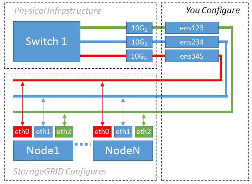
Example 1 describes a simple physical interface mapping that requires little or no host-side configuration.

The Linux operating system creates the ensXYZ interfaces automatically during installation or boot, or when the interfaces are hot-added. No configuration is required other than ensuring that the interfaces are set to come up automatically after boot. You do have to determine which ensXYZ corresponds to which StorageGRID network (Grid, Admin, or Client) so you can provide the correct mappings later in the configuration process.
Note that the figure show multiple StorageGRID nodes; however, you would normally use this configuration for single-node VMs.
If Switch 1 is a physical switch, you should configure the ports connected to interfaces 10G1 through 10G3 for access mode, and place them on the appropriate VLANs.
Example 2: LACP bond carrying VLANs
Example 2 assumes you are familiar with bonding network interfaces and with creating VLAN interfaces on the Linux distribution you are using.
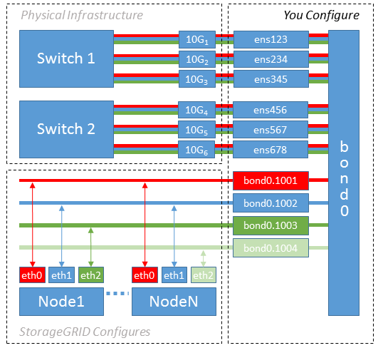
Example 2 describes a generic, flexible, VLAN-based scheme that facilitates the sharing of all available network bandwidth across all nodes on a single host. This example is particularly applicable to bare metal hosts.
To understand this example, suppose you have three separate subnets for the Grid, Admin, and Client Networks at each data center. The subnets are on separate VLANs (1001, 1002, and 1003) and are presented to the host on a LACP-bonded trunk port (bond0). You would configure three VLAN interfaces on the bond: bond0.1001, bond0.1002, and bond0.1003.
If you require separate VLANs and subnets for node networks on the same host, you can add VLAN interfaces on the bond and map them into the host (shown as bond0.1004 in the illustration).

-
Aggregate all physical network interfaces that will be used for StorageGRID network connectivity into a single LACP bond.
Use the same name for the bond on every host. For example,
bond0. -
Create VLAN interfaces that use this bond as their associated “physical device,” using the standard VLAN interface naming convention
physdev-name.VLAN ID.Note that steps 1 and 2 require appropriate configuration on the edge switches terminating the other ends of the network links. The edge switch ports must also be aggregated into a LACP port channel, configured as a trunk, and allowed to pass all required VLANs.
Sample interface configuration files for this per-host networking configuration scheme are provided.


