

Replace E2800 series storage controller in the SG5700
 Suggest changes
You might need to replace the E2800 series controller if it is not functioning optimally or if it has failed.
-
You have a replacement controller with the same part number as the controller you are replacing.

Don't rely on the E-Series instructions to replace a controller in the StorageGRID appliance, because the procedures aren't the same. -
You have labels to identify each cable that is connected to the controller.
-
If all drives are secured, you have reviewed the steps in the simplex E2800 series controller replacement procedure, which include downloading and installing E-Series SANtricity System Manager from the NetApp Support Site and then using the Enterprise Management Window (EMW) to unlock the secured drives after you have replaced the controller.
You will not be able to use the appliance until you unlock the drives with the saved key. -
You must have specific access permissions.
-
You must be signed in to the Grid Manager using a supported web browser.
You can determine if you have a failed controller canister in two ways:
-
The Recovery Guru in SANtricity System Manager directs you to replace the controller.
-
The amber Attention LED on the controller is on, indicating that the controller has a fault.
The appliance Storage Node will not be accessible when you replace the controller. If the E2800 series controller is functioning sufficiently, you can place the E5700SG controller into maintenance mode.
When you replace a controller, you must remove the battery from the original controller and install it in the replacement controller. In some cases, you might also need to remove the host interface card from the original controller and install it in the replacement controller.

|
The storage controllers in most appliance models don't include host interface cards (HIC). |
Step 1: Prepare to remove the controller
These figures show the E2800A controller and the E2800B controller. The procedure for replacing the E2800 series controllers and the EF570 controller is identical.
E2800A storage controller:
E2800B storage controller:
| Label | component | Description |
|---|---|---|
1 |
MAC address |
The MAC address for management port 1 (“P1 on the E2800A and 0a on the E2800B”). If you used DHCP to obtain the original controller's IP address, you will need this address to connect to the new controller. |
2 |
FRU part number |
The FRU part number. This number must match the replacement part number for the currently installed controller. |
3 |
4-port HIC |
The 4-port host interface card (HIC). This card must be moved to the new controller when you perform the replacement. Note: the E2800A controller does not have a HIC. |
Follow the instructions in the E2800 controller replacement procedure to prepare to remove the controller.
You use SANtricity System Manager to perform these steps.
-
Make a note of which version of SANtricity OS software is currently installed on the controller.
-
Make a note of which version of NVSRAM is currently installed.
-
If the Drive Security feature is enabled, be sure a saved key exists and that you know the pass phrase required to install it.
Possible loss of data access — If all drives in the appliance are security enabled, the new controller will not be able to access the appliance until you unlock the secured drives using the Enterprise Management Window in SANtricity System Manager. -
Back up the configuration database.
If a problem occurs when you remove a controller, you can use the saved file to restore your configuration.
-
Collect support data for the appliance.
Collecting support data before and after replacing a component ensures you can send a full set of logs to technical support if the replacement does not resolve the problem.
Step 2: Take the controller offline
Take the controller offline and confirm that all operations are complete.
-
If the StorageGRID appliance is running in a StorageGRID system, place the E5700SG controller into maintenance mode.
-
If the E2800 controller is functioning sufficiently to allow for a controlled shutdown, confirm that all operations have completed.
-
From the home page of SANtricity System Manager, select View Operations in Progress.
-
Confirm that all operations have completed.
-
Power off the controller shelf.
Step 3: Remove the controller
Remove the controller from the appliance.
-
Put on an ESD wristband or take other antistatic precautions.
-
Label the cables and then disconnect the cables and SFPs.
To prevent degraded performance, don't twist, fold, pinch, or step on the cables. -
Release the controller from the appliance by squeezing the latch on the cam handle until it releases, and then open the cam handle to the right.
-
Using two hands and the cam handle, slide the controller out of the appliance.
Always use two hands to support the weight of the controller. -
Place the controller on a flat, static-free surface with the removable cover facing up.
-
Remove the cover by pressing down on the button and sliding the cover off.
Step 4: Move battery to the new controller
Remove the battery from the failed controller, and install it into the replacement controller.
-
Confirm that the green LED inside the controller (between the battery and the DIMMs) is off.
If this green LED is on, the controller is still using battery power. You must wait for this LED to go off before removing any components.
Item Description 1
Internal Cache Active LED
2
Battery
-
Locate the blue release latch for the battery.
-
Unlatch the battery by pushing the release latch down and away from the controller.
Item Description 1
Battery release latch
2
Battery
-
Lift up on the battery, and slide it out of the controller.
-
Remove the cover from the replacement controller.
-
Orient the replacement controller so that the slot for the battery faces toward you.
-
Insert the battery into the controller at a slight downward angle.
You must insert the metal flange at the front of the battery into the slot on the bottom of the controller, and slide the top of the battery beneath the small alignment pin on the left side of the controller.
-
Move the battery latch up to secure the battery.
When the latch clicks into place, the bottom of the latch hooks into a metal slot on the chassis.
-
Turn the controller over to confirm that the battery is installed correctly.
Possible hardware damage — The metal flange at the front of the battery must be completely inserted into the slot on the controller (as shown in the first figure). If the battery is not installed correctly (as shown in the second figure), the metal flange might contact the controller board, causing damage. -
Correct — The battery's metal flange is completely inserted into the slot on the controller:
-
Incorrect — The battery's metal flange is not inserted into the slot on the controller:
-
-
Replace the controller cover.
Step5: Move HIC to new controller, if needed
If the failed controller includes a host interface card (HIC), move the HIC from the failed controller to the replacement controller.
A separate HIC is used for the E2800B controller only. The HIC is mounted to the main controller board and includes two SPF connectors.
|
|
The illustrations in this procedure show a 2-port HIC. The HIC in your controller might have a different number of ports. |
An E2800A controller does not have a HIC.
Replace the E2800A controller cover, and go to Step 6: Replace controller
Move the HIC from the failed E2800B controller to the replacement controller.
-
Remove any SFPs from the HIC.
-
Using a #1 Phillips screwdriver, remove the screws that attach the HIC faceplate to the controller.
There are four screws: one on the top, one on the side, and two on the front.
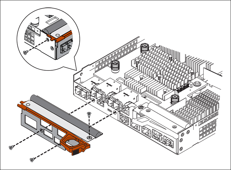
-
Remove the HIC faceplate.
-
Using your fingers or a Phillips screwdriver, loosen the three thumbscrews that secure the HIC to the controller card.
-
Carefully detach the HIC from the controller card by lifting the card up and sliding it back.

Be careful not to scratch or bump the components on the bottom of the HIC or on the top of the controller card. 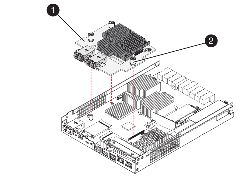
Label Description 1
Host interface card
2
Thumbscrews
-
Place the HIC on a static-free surface.
-
Using a #1 Phillips screwdriver, remove the four screws that attach the blank faceplate to the replacement controller, and remove the faceplate.
-
Align the three thumbscrews on the HIC with the corresponding holes on the replacement controller, and align the connector on the bottom of the HIC with the HIC interface connector on the controller card.
Be careful not to scratch or bump the components on the bottom of the HIC or on the top of the controller card.
-
Carefully lower the HIC into place, and seat the HIC connector by pressing gently on the HIC.
Possible equipment damage — Be careful not to pinch the gold ribbon connector for the controller LEDs between the HIC and the thumbscrews. 
Label Description 1
Host interface card
2
Thumbscrews
-
Hand-tighten the HIC thumbscrews.
Don't use a screwdriver, or you might over tighten the screws.
-
Using a #1 Phillips screwdriver, attach the HIC faceplate you removed from the original controller to the new controller with four screws.
-
Reinstall any removed SFPs into the HIC.
Step 6: Replace controller
Install the replacement controller and verify that it has rejoined the grid.
-
Install the replacement controller into the appliance.
-
Turn the controller over, so that the removable cover faces down.
-
With the cam handle in the open position, slide the controller all the way into the appliance.
-
Move the cam handle to the left to lock the controller in place.
-
Replace the cables and SFPs.
-
Power on the controller shelf.
-
Wait for the E2800 controller to reboot. Verify that the seven-segment display shows a state of
99. -
Determine how you will assign an IP address to the replacement controller.
The steps for assigning an IP address to the replacement controller depend on whether you connected management port 1 to a network with a DHCP server and on whether all drives are secured. If management port 1 is connected to a network with a DHCP server, the new controller will obtain its IP address from the DHCP server. This value might be different than the original controller's IP address.
-
-
If the appliance uses secured drives, follow the instructions in the E2800 controller replacement procedure to import the drive security key.
-
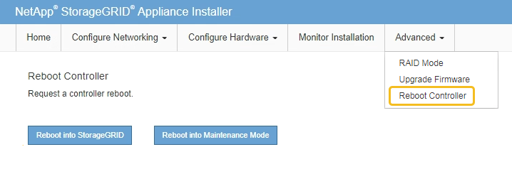
Return the appliance to normal operating mode. From the StorageGRID Appliance Installer, select Advanced > Reboot Controller, and then select Reboot into StorageGRID.
-
During the reboot, monitor the node's status to determine when it has rejoined the grid.
The appliance reboots and rejoins the grid. This process can take up to 20 minutes.
-
Confirm that the reboot is complete and that the node has rejoined the grid. In the Grid Manager, verify that the Nodes page displays a normal status (green check mark icon
 to the left of the node name) for the appliance node, indicating that no alerts are active and the node is connected to the grid.
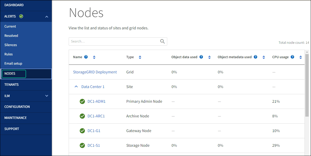
-
From SANtricity System Manager, confirm that the new controller is Optimal, and collect support data.
After replacing the part, return the failed part to NetApp, as described in the RMA instructions shipped with the kit. See the Part Return & Replacements page for further information.