

Segregate SnapMirror traffic in Azure
 Suggest changes
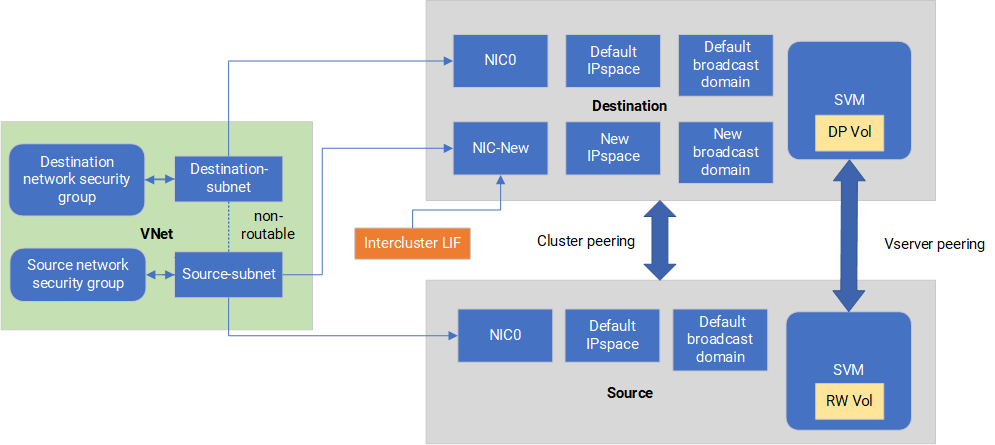
With Cloud Volumes ONTAP in Azure, you can segregate SnapMirror replication traffic from data and management traffic. To segregate SnapMirror replication traffic from your data traffic, you'll add a new network interface card (NIC), an associated intercluster LIF and a non-routable subnet.
About SnapMirror traffic segregation in Azure
By default, the NetApp Console configures all NICs and LIFs in a Cloud Volumes ONTAP deployment on the same subnet. In such configurations, SnapMirror replication traffic and data and management traffic use the same subnet. Segregating SnapMirror traffic leverages an additional subnet that isn't routable to the existing subnet used for data and management traffic.
The following diagrams show the segregation of SnapMirror replication traffic with an additional NIC, an associated intercluster LIF and a non-routable subnet in a single node deployment. An HA pair deployment differs slightly.
Review the following considerations:
-
You can only add a single NIC to a Cloud Volumes ONTAP single node or HA-pair deployment (VM instance) for SnapMirror traffic segregation.
-
To add a new NIC, the VM instance type you deploy must have an unused NIC.
-
The source and destination clusters should have access to the same Virtual Network (VNet). The destination cluster is a Cloud Volumes ONTAP system in Azure. The source cluster can be a Cloud Volumes ONTAP system in Azure or an ONTAP system.
Step 1: Create an additional NIC and attach to the destination VM
This section provides instructions for how to create an additional NIC and attach it to the destination VM. The destination VM is the single node or HA-pair system in Cloud Volumes ONTAP in Azure where you want to set up your additional NIC.
-
In the ONTAP CLI, stop the node.
dest::> halt -node <dest_node-vm> -
In the Azure portal, check that the VM (node) status is stopped.
az vm get-instance-view --resource-group <dest-rg> --name <dest-vm> --query instanceView.statuses[1].displayStatus -
Use the Bash environment in Azure Cloud Shell to stop the node.
-
Stop the node.
az vm stop --resource-group <dest_node-rg> --name <dest_node-vm> -
Deallocate the node.
az vm deallocate --resource-group <dest_node-rg> --name <dest_node-vm>
-
-
Configure network security group rules to make the two subnets (source cluster subnet and destination cluster subnet) non-routable to each other.
-
Create the new NIC on the destination VM.
-
Look up the subnet ID for the source cluster subnet.
az network vnet subnet show -g <src_vnet-rg> -n <src_subnet> --vnet-name <vnet> --query id -
Create the new NIC on the destination VM with the subnet ID for the source cluster subnet. Here you enter the name for the new NIC.
az network nic create -g <dest_node-rg> -n <dest_node-vm-nic-new> --subnet <id_from_prev_command> --accelerated-networking true -
Save the privateIPAddress. This IP address, <new_added_nic_primary_addr>, is used to create an intercluster LIF in broadcast domain, intercluster LIF for the new NIC.
-
-
Attach the new NIC to the VM.
az vm nic add -g <dest_node-rg> --vm-name <dest_node-vm> --nics <dest_node-vm-nic-new> -
Start the VM (node).
az vm start --resource-group <dest_node-rg> --name <dest_node-vm> -
In the Azure portal, go to Networking and confirm that the new NIC, e.g. nic-new, exists and accelerated networking is enabled.
az network nic list --resource-group azure-59806175-60147103-azure-rg --query "[].{NIC: name, VM: virtualMachine.id}"
For HA-pair deployments, repeat the steps for the partner node.
Step 2: Create a new IPspace, broadcast domain, and intercluster LIF for the new NIC
A separate IPspace for intercluster LIFs provides logical separation between networking functionality for replication between clusters.
Use the ONTAP CLI for the following steps.
-
Create the new IPspace (new_ipspace).
dest::> network ipspace create -ipspace <new_ipspace> -
Create a broadcast domain on the new IPspace (new_ipspace) and add the nic-new port.
dest::> network port show -
For single-node systems, the newly added port is e0b. For HA-pair deployments with managed disks, the newly added port is e0d. For HA-pair deployments with page blobs, the newly added port is e0e. Use the node name not the VM name. Find the node name by running
node show.dest::> broadcast-domain create -broadcast-domain <new_bd> -mtu 1500 -ipspace <new_ipspace> -ports <dest_node-cot-vm:e0b> -
Create an intercluster LIF on the new broadcast-domain (new_bd) and on the new NIC (nic-new).
dest::> net int create -vserver <new_ipspace> -lif <new_dest_node-ic-lif> -service-policy default-intercluster -address <new_added_nic_primary_addr> -home-port <e0b> -home-node <node> -netmask <new_netmask_ip> -broadcast-domain <new_bd> -
Verify creation of the new intercluster LIF.
dest::> net int show
For HA-pair deployments, repeat the steps for the partner node.
Step 3: Verify cluster peering between the source and destination systems
This section provides instructions for how to verify peering between the source and destination systems.
Use the ONTAP CLI for the following steps.
-
Verify that the intercluster LIF of the destination cluster can ping the intercluster LIF of the source cluster. Because the destination cluster executes this command, the destination IP address is the intercluster LIF IP address on the source.
dest::> ping -lif <new_dest_node-ic-lif> -vserver <new_ipspace> -destination <10.161.189.6> -
Verify that the intercluster LIF of the source cluster can ping the intercluster LIF of the destination cluster. The destination is the IP address of the new NIC created on the destination.
src::> ping -lif <src_node-ic-lif> -vserver <src_svm> -destination <10.161.189.18>
For HA-pair deployments, repeat the steps for the partner node.
Step 4: Create SVM peering between the source and destination system
This section provides instructions for how to create SVM peering between the source and destination system.
Use the ONTAP CLI for the following steps.
-
Create cluster peering on the destination using the source intercluster LIF IP address as the
-peer-addrs. For HA pairs, list the source intercluster LIF IP address for both nodes as the-peer-addrs.dest::> cluster peer create -peer-addrs <10.161.189.6> -ipspace <new_ipspace> -
Enter and confirm the passphrase.
-
Create cluster peering on the source using the destination cluster LIF IP address as the
peer-addrs. For HA pairs, list the destination intercluster LIF IP address for both nodes as the-peer-addrs.src::> cluster peer create -peer-addrs <10.161.189.18> -
Enter and confirm the passphrase.
-
Check that the cluster peered.
src::> cluster peer showSuccessful peering shows Available in the availability field.
-
Create SVM peering on the destination. Both source and destination SVMs should be data SVMs.
dest::> vserver peer create -vserver <dest_svm> -peer-vserver <src_svm> -peer-cluster <src_cluster> -applications snapmirror`` -
Accept SVM peering.
src::> vserver peer accept -vserver <src_svm> -peer-vserver <dest_svm> -
Check that the SVM peered.
dest::> vserver peer showPeer state shows
peeredand peering applications showssnapmirror.
Step 5: Create a SnapMirror replication relationship between the source and destination system
This section provides instructions for how to create a SnapMirror replication relationship between the source and destination system.
To move an existing SnapMirror replication relationship, you must first break the existing SnapMirror replication relationship before you create a new SnapMirror replication relationship.
Use the ONTAP CLI for the following steps.
-
Create a data protected volume on the destination SVM.
dest::> vol create -volume <new_dest_vol> -vserver <dest_svm> -type DP -size <10GB> -aggregate <aggr1> -
Create the SnapMirror replication relationship on the destination which includes the SnapMirror policy and schedule for the replication.
dest::> snapmirror create -source-path src_svm:src_vol -destination-path dest_svm:new_dest_vol -vserver dest_svm -policy MirrorAllSnapshots -schedule 5min -
Initialize the SnapMirror replication relationship on the destination.
dest::> snapmirror initialize -destination-path <dest_svm:new_dest_vol> -
In the ONTAP CLI, validate the SnapMirror relationship status by running the following command:
dest::> snapmirror showThe relationship status is
Snapmirroredand the health of the relationship istrue. -
Optional: In the ONTAP CLI, run the following command to view the actions history for the SnapMirror relationship.
dest::> snapmirror show-history
Optionally, you can mount the source and destination volumes, write a file to the source, and verify the volume is replicating to the destination.