

 Upgrade by using aggregate relocation
Replace the node1 system modules
 Suggest changes
Replace the node1 system modules for your upgrade configuration:
-
Replace the AFF A220, AFF A200, AFF C190, FAS2620, or FAS2720 controller module

You can also use this procedure to replace an AFF A220 configured as an ASA. -
Replace the AFF A700 or FAS9000 controller and NVRAM modules
You can also use this procedure to replace an AFF A700 configured as an ASA.
Replace the AFF A220, AFF A200, AFF C190, FAS2620, or FAS2720 controller module
At this stage, node1 is down and all data is served by node2. Because node1 and node2 are in the same chassis and powered by the same set of power supplies, do NOT power off the chassis. You must take care to remove only the node1 controller module. Typically, node1 is controller A, located on the left side of the chassis when looking at the controllers from the rear of the system. The controller label is located on the chassis directly above the controller module.
If you are not already grounded, correctly ground yourself.
Remove the AFF A220, AFF A200, AFF C190, FAS2620, or FAS2720 controller module
To access components inside the controller, you must first remove the controller module from the system and then remove the cover on the controller module.
-
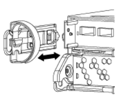
Loosen the hook and loop strap binding the cables to the cable management device, and then unplug the system cables and SFPs (if needed) from the controller module, keeping track of where the cables were connected.
Leave the cables in the cable management device so that when you reinstall the cable management device, the cables are organized.
-
Remove and set aside the cable management devices from the left and right sides of the controller module.
-
Squeeze the latch on the cam handle until it releases, open the cam handle fully to release the controller module from the midplane, and then, using two hands, pull the controller module out of the chassis.
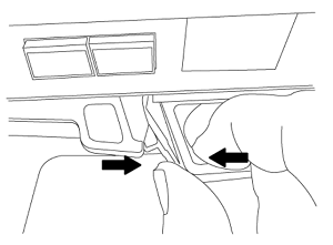
-
Turn the controller module over and place it on a flat, stable surface.
Install the ASA A150, AFF A150, or FAS2820 controller module
Use the following procedure to install the ASA A150, AFF A150, or FAS2820 controller module in node1.
-
Align the end of the controller module with the opening in the chassis, and then gently push the controller module halfway into the system.
Do not completely insert the controller module in the chassis until instructed to do so later in the procedure. -
Cable the management and console ports to the node1 controller module.
Because the chassis is already powered ON, node1 starts BIOS initialization followed by autoboot as soon as it is fully seated. To interrupt the node1 boot, before completely inserting the controller module into the slot, it is recommended that you connect the serial console and management cables to the node1 controller module. -
With the cam handle in the open position, firmly push the controller module in until it meets the midplane and is fully seated. The locking latch rises when the controller module is fully seated. Close the cam handle to the locked position.
To avoid damaging the connectors, do not use excessive force when sliding the controller module into the chassis. -
Connect the serial console as soon as the module is seated and be ready to interrupt AUTOBOOT of node1.
-
After you interrupt AUTOBOOT, node1 stops at the LOADER prompt. If you do not interrupt AUTOBOOT on time and node1 starts booting, wait for the prompt and press Ctrl-C to go into the boot menu. After the node stops at the boot menu, use option 8 to reboot the node and interrupt the AUTOBOOT during reboot.
-
At the LOADER> prompt of node1, set the default environment variables:
set-defaults -
Save the default environment variables settings:
saveenv
Replace the AFF A700 or FAS9000 controller and NVRAM modules
At this stage, node1 is down and all data is served by node2. Because node1 and node2 are in the same chassis and powered by the same set of power supplies, do NOT power off the chassis. You must take care to remove only the node1 controller module and the node1 NVRAM module. Typically, node1 is controller A, located on the left side of the chassis when looking at the controllers from the rear of the system. The controller label is located on the chassis directly above the controller module.
If you are not already grounded, correctly ground yourself.
Remove the AFF A700 or FAS9000 controller module
Use the following procedure to remove the AFF A700 or FAS9000 controller module.
-
Detach the console cable, if any, and the management cable from the node1 controller module before removing the controller module from node1.

When you are working on node1, you only remove the console and e0M cables from node1. You must not remove or change any other cables or connections on either node1 or node2 during this process. -
Unlock and remove the controller module A from the chassis.
-
Slide the orange button on the cam handle downward until it unlocks.
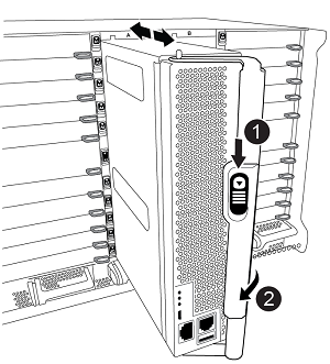

Cam handle release button

Cam handle
-
Rotate the cam handle so that it completely disengages the controller module from the chassis, and then slide the controller module out of the chassis.
Make sure that you support the bottom of the controller module as you slide it out of the chassis.
-
Remove the AFF A700 or FAS9000 NVRAM module
Use the following procedure to remove the AFF A700 or FAS9000 NVRAM module.
|
|
The AFF A700 or FAS9000 NVRAM module is in slot 6 and is double the height of the other modules in the system. |
-
Unlock and remove the NVRAM module from slot 6 of node1.
-
Depress the lettered and numbered cam button.
The cam button moves away from the chassis.
-
Rotate the cam latch down until it is in a horizontal position.
The NVRAM module disengages from the chassis and moves a few inches.
-
Remove the NVRAM module from the chassis by pulling on the pull tabs on the sides of the module face.
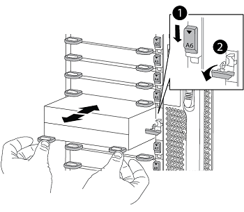
Lettered and numbered I/O cam latch
I/O latch completely unlocked
-
Install the ASA A900, AFF A900, or FAS9500 NVRAM and controller modules
Install the ASA A900, AFF A900, or FAS9500 NVRAM and controller modules that you received for the upgrade on node1.
You must note the following when performing the installation:
-
Move all blank filler modules in slots 6-1 and 6-2 from the old NVRAM module to the new NVRAM module.
-
Do NOT move the coredump device from the AFF A700 NVRAM module to the ASA A900 or AFF A900 NVRAM module.
-
Move all flash cache modules installed in the FAS9000 NVRAM module to the FAS9500 NVRAM module.
If you are not already grounded, correctly ground yourself.
Install the ASA A900, AFF A900, or FAS9500 NVRAM module
Use the following procedure to install the ASA A900, AFF A900, or FAS9500 NVRAM module in slot 6 of node1.
-
Align the NVRAM module with the edges of the chassis opening in slot 6.
-
Gently slide the NVRAM module into the slot until the lettered and numbered I/O cam latch begins to engage with the I/O cam pin, and then push the I/O cam latch all the way up to lock the NVRAM module in place.
Lettered and numbered I/O cam latch
I/O latch completely unlocked
Install the ASA A900, AFF A900, or FAS9500 controller module on node1.
Use the following procedure to install the ASA A900, AFA A900, or FAS9500 controller module in node1.
-
Align the end of the controller module with opening A in the chassis, and then gently push the controller module halfway into the system.
Do not completely insert the controller module in the chassis until instructed to do so later in the procedure. -
Cable the management and console ports to the node1 controller module.
Because the chassis is already powered ON, node1 starts BIOS initialization followed by autoboot as soon as it is fully seated. To interrupt the node1 boot, before completely inserting the controller module into the slot, it is recommended that you connect the serial console and management cables to the node1 controller module. -
Firmly push the controller module into the chassis until it meets the midplane and is fully seated.
The locking latch rises when the controller module is fully seated.
To avoid damaging the connectors, do not use excessive force when sliding the controller module into the chassis.
Cam handle locking latch
Cam handle in the unlocked position
-
Connect the serial console as soon as the module is seated and be ready to interrupt AUTOBOOT of node1.
-
After you interrupt AUTOBOOT, node1 stops at the LOADER prompt. If you do not interrupt AUTOBOOT on time and node1 starts booting, wait for the prompt and press Ctrl-C to go into the boot menu. After the node stops at the boot menu, use option
8to reboot the node and interrupt the AUTOBOOT during reboot. -
At the LOADER> prompt of node1, set the default environment variables:
set-defaults -
Save the default environment variables settings:
saveenv