

 使用聚合重新定位进行升级
更换node1系统模块
 建议更改
建议更改
更换适用于您的升级配置的node1系统模块:
-
更换AFF A220、AFF A200、AFF C190、FAS2620或FAS2720控制器模块

您还可以使用此操作步骤更换配置为ASA的AFF A220。 -
您还可以使用此操作步骤替换配置为ASA的AFF A700。
更换AFF A220、AFF A200、AFF C190、FAS2620或FAS2720控制器模块
在此阶段, node1 已关闭,所有数据均由 node2 提供。由于 node1 和 node2 位于同一机箱中,并由同一组电源供电,因此请勿关闭机箱电源。您必须小心地仅卸下node1控制器模块。通常, node1 是控制器 A ,位于机箱左侧,用于从系统背面查看控制器。控制器标签位于机箱上,控制器模块正上方。
如果您尚未接地,请正确接地。
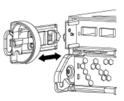
卸下AFF A220、AFF A200、AFF C190、FAS2620或FAS2720控制器模块
To access components inside the controller, you must first remove the controller module from the system and then remove the cover on the controller module.
-
Loosen the hook and loop strap binding the cables to the cable management device, and then unplug the system cables and SFPs (if needed) from the controller module, keeping track of where the cables were connected.
Leave the cables in the cable management device so that when you reinstall the cable management device, the cables are organized.
-
Remove and set aside the cable management devices from the left and right sides of the controller module.
-
Squeeze the latch on the cam handle until it releases, open the cam handle fully to release the controller module from the midplane, and then, using two hands, pull the controller module out of the chassis.
-
Turn the controller module over and place it on a flat, stable surface.
安装ASA A150、AFF A150或FAS2820控制器模块
使用以下操作步骤在node1中安装ASA A150、AFF A150或FAS2820控制器模块。
-
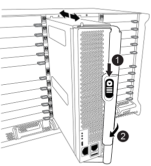
Align the end of the controller module with the opening in the chassis, and then gently push the controller module halfway into the system.
请勿将控制器模块完全插入机箱,除非稍后在操作步骤 中指示您这样做。 -
使用缆线将管理和控制台端口连接到 node1 控制器模块。
由于机箱已启动, node1 将启动 BIOS 初始化,然后在完全就位后立即启动自动启动。要中断 node1 启动,在将控制器模块完全插入插槽之前,建议将串行控制台和管理缆线连接到 node1 控制器模块。 -
在凸轮把手处于打开位置的情况下、用力推入控制器模块、直至其与中板接触并完全就位。控制器模块完全就位后,锁定闩锁会上升。将凸轮把手关闭至锁定位置。
为避免损坏连接器,请勿在将控制器模块滑入机箱时用力过大。 -
一旦模块就位,请立即连接串行控制台,并准备好中断 node1 的自动启动。
-
中断自动启动后, node1 将停留在 LOADER 提示符处。如果不中断自动启动,而 node1 开始启动,请等待提示符,然后按 * Ctrl-C* 进入启动菜单。在节点停留在启动菜单处后、使用选项8重新启动节点、并在重新启动期间中断自动启动。
-
在 LOADER 提示符 node1 处,设置默认环境变量:
set-defaults -
保存默认环境变量设置:
saveenv
更换AFF A700或FAS9000控制器和NVRAM模块
在此阶段, node1 已关闭,所有数据均由 node2 提供。由于 node1 和 node2 位于同一机箱中,并由同一组电源供电,因此请勿关闭机箱电源。您必须小心地仅卸下 node1 控制器模块和 node1 NVRAM 模块。通常, node1 是控制器 A ,位于机箱左侧,用于从系统背面查看控制器。控制器标签位于机箱上,控制器模块正上方。
如果您尚未接地,请正确接地。
卸下AFF A700或FAS9000控制器模块
使用以下操作步骤 删除AFF A700或FAS9000控制器模块。
-
从 node1 控制器模块中卸下控制器模块之前,请断开控制台缆线(如果有)和管理缆线与 node1 控制器模块的连接。

在处理 node1 时,只需从 node1 中拔下控制台和 e0M 缆线。在此过程中,您不能移除或更改 node1 或 node2 上的任何其他缆线或连接。 -
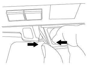
解锁控制器模块 A 并将其从机箱中卸下。
-
Slide the orange button on the cam handle downward until it unlocks.

Cam handle release button

Cam handle
-
Rotate the cam handle so that it completely disengages the controller module from the chassis, and then slide the controller module out of the chassis.
Make sure that you support the bottom of the controller module as you slide it out of the chassis.
-
卸下AFF A700或FAS9000 NVRAM模块
使用以下操作步骤 删除AFF A700或FAS9000 NVRAM模块。
|
|
AFF A700或FAS9000 NVRAM模块位于插槽6中、高度是系统中其他模块的两倍。 |
-
从 node1 的插槽 6 中解锁 NVRAM 模块并将其卸下。
-
Depress the lettered and numbered cam button.
The cam button moves away from the chassis.
-
Rotate the cam latch down until it is in a horizontal position.
NVRAM 模块从机箱中分离并移动几英寸。
-
Remove the NVRAM module from the chassis by pulling on the pull tabs on the sides of the module face.
Lettered and numbered I/O cam latch
I/O latch completely unlocked
-
安装ASA A900、AFF A900或FAS9500 NVRAM和控制器模块
在node1上安装为升级而收到的ASA A900、AFF A900或FAS9500 NVRAM和控制器模块。
执行安装时、必须注意以下事项:
-
将插槽6-1和6-2中的所有空白填充模块从旧NVRAM模块移至新的NVRAM模块。
-
请勿将核心转储设备从AFF A700 NVRAM模块移至ASA A900或AFF A900 NVRAM模块。
-
将FAS9000 NVRAM模块中安装的所有闪存缓存模块移至FAS9500NVRAM模块。
如果您尚未接地,请正确接地。
安装ASA A900、AFF A900或FAS9500 NVRAM模块
使用以下操作步骤将ASA A900、AFF A900或FAS9500 NVRAM模块安装到node1的插槽6中。
-
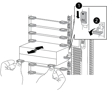
将 NVRAM 模块与插槽 6 中机箱开口的边缘对齐。
-
将 NVRAM 模块轻轻滑入插槽,直到带字母和编号的 I/O 凸轮闩锁开始与 I/O 凸轮销啮合,然后将 I/O 凸轮闩锁一直向上推,以将 NVRAM 模块锁定到位。
Lettered and numbered I/O cam latch
I/O latch completely unlocked
在node1上安装ASA A900、AFF A900或FAS9500控制器模块。
使用以下操作步骤在node1中安装ASA A900、AFA A900或FAS9500控制器模块。
-
将控制器模块的末端与机箱中的开口对齐,然后将控制器模块轻轻推入系统的一半。
请勿将控制器模块完全插入机箱,除非稍后在操作步骤 中指示您这样做。 -
使用缆线将管理和控制台端口连接到 node1 控制器模块。
由于机箱已启动, node1 将启动 BIOS 初始化,然后在完全就位后立即启动自动启动。要中断 node1 启动,在将控制器模块完全插入插槽之前,建议将串行控制台和管理缆线连接到 node1 控制器模块。 -
Firmly push the controller module into the chassis until it meets the midplane and is fully seated.
控制器模块完全就位后,锁定闩锁会上升。
为避免损坏连接器,请勿在将控制器模块滑入机箱时用力过大。
凸轮把手锁定闩锁
凸轮把手处于解锁位置
-
一旦模块就位,请立即连接串行控制台,并准备好中断 node1 的自动启动。
-
中断自动启动后, node1 将停留在 LOADER 提示符处。如果不中断自动启动,而 node1 开始启动,请等待提示符,然后按 * Ctrl-C* 进入启动菜单。在节点停留在启动菜单后,使用选项
8重新启动节点,并在重新启动期间中断自动启动。 -
在 LOADER 提示符 node1 处,设置默认环境变量:
set-defaults -
保存默认环境变量设置:
saveenv