

 Get started
Hardware configuration
 Suggest changes
The hardware configuration for BeeGFS on NetApp includes file nodes and network cabling.
File node configuration
File nodes have two CPU sockets configured as separate NUMA zones, which include local access to an equal number of PCIe slots and memory.
InfiniBand adapters must be populated in the appropriate PCI risers or slots, so the workload is balanced over the available PCIe lanes and memory channels. You balance the workload by fully isolating work for individual BeeGFS services to a particular NUMA node. The goal is to achieve similar performance from each file node as if it were two independent single socket servers.
The following figure shows the file node NUMA configuration.
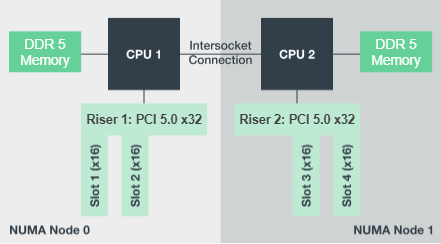
The BeeGFS processes are pinned to a particular NUMA zone to ensure that the interfaces used are in the same zone. This configuration avoids the need for remote access over the inter-socket connection. The inter-socket connection is sometimes known as the QPI or GMI2 link; even in modern processor architectures, they can be a bottleneck when using high-speed networking like HDR InfiniBand.
Network cabling configuration
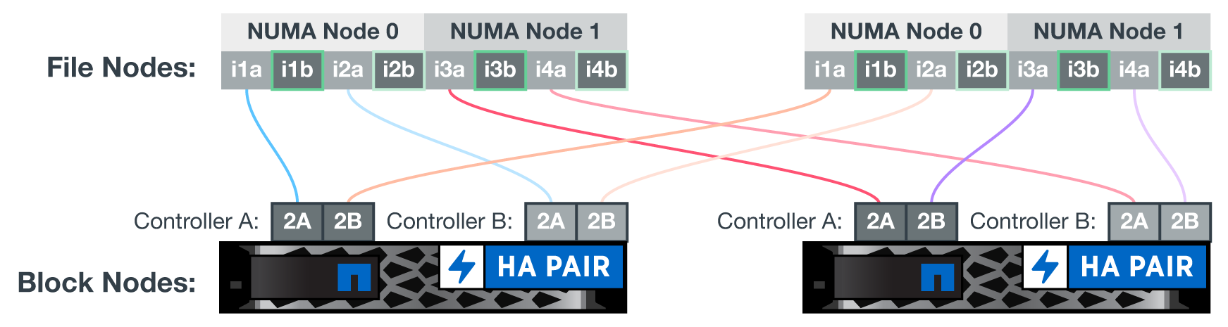
Within a building block, each file node is connected to two block nodes using a total of four redundant InfiniBand connections. In addition, each file node has four redundant connections to the InfiniBand storage network.
In the following figure, notice that:
-
All file node ports outlined in green are used to connect to the storage fabric; all other file node ports are the direct connects to the block nodes.
-
Two InfiniBand ports in a specific NUMA zone connect to the A and B controllers of the same block node.
-
Ports in NUMA node 0 always connect to the first block node.
-
Ports in NUMA node 1 connect to the second block node.

|
For storage networks with redundant switches, ports outlined in light green should connect to one switch, and ports in dark green to another switch. |
The cabling configuration depicted in the figure allows each BeeGFS service to:
-
Run in the same NUMA zone regardless of which file node is running the BeeGFS service.
-
Have secondary optimal paths to the front-end storage network and to the back-end block nodes regardless of where a failure occurs.
-
Minimize performance effects if a file node or controller in a block node requires maintenance.
To leverage the full PCIe bidirectional bandwidth, make sure one port on each InfiniBand adapter connects to the storage fabric, and the other port connects to a block node. The theoretical maximum speed of an HDR InfiniBand port is 25GBps (not accounting for signaling and other overhead). The maximum single direction bandwidth of a PCIe 4.0 x16 slot is 32GBps, creating a potential bottleneck when implementing file nodes that incorporate dual port InfiniBand adapters that can theoretically handle 50GBps of bandwidth.
The following figure shows the cabling design used to leverage the full PCIe bidirectional bandwidth.
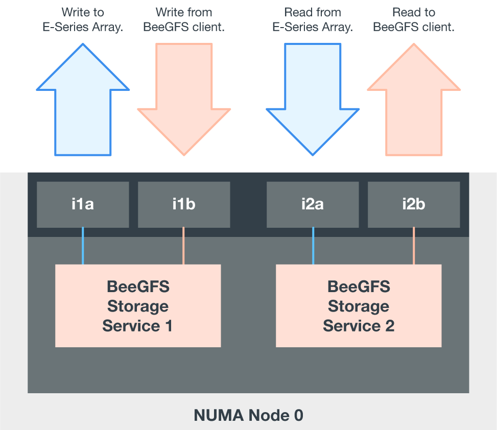
For each BeeGFS service, use the same adapter to connect the preferred port used for client traffic with the path to the block nodes controller that is the primary owner of that services volumes. For more information, see Software configuration.