

Network configuration
 Suggest changes
NetApp HCI can utilize multiple different network cabling and VLAN configurations. The first configuration, option A, uses two network cables for each compute node.
Configuration option A: Two cables for compute nodes
The NetApp H410C, H610C, and H615C compute nodes support using two network cables for connectivity to all NetApp HCI networks. This configuration requires that the storage, vMotion and any virtual machine networks use VLAN tagging. All compute and storage nodes must use the same VLAN ID scheme. This configuration uses vSphere Distributed Switches that require VMware vSphere Enterprise Plus licensing.
NetApp HCI documentation uses letters to refer to network ports on the back panel of H-series nodes.
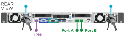
Here are the network ports and locations on the H410C storage node:
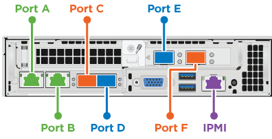
Here are the network ports and locations on the H610C compute node:
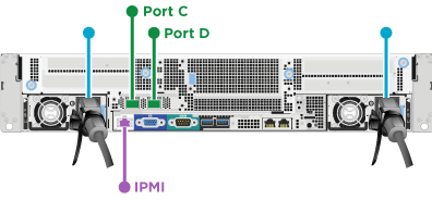
Here are the network ports and locations on the H615C compute node:
This configuration uses the following network ports on each node:
| Node | Network ports used |
|---|---|
H410C |
D and E |
H610C |
C and D |
H615C |
A and B |
VLAN configuration
As a best practice, you should configure the required network segments on all switch ports that the nodes are using. For example:
| Network name | VLAN ID | Switch port configuration |
|---|---|---|
Management |
100 |
Native |
Storage |
105 |
Tagged |
vMotion |
107 |
Tagged |
Virtual machines |
200, 201 |
Tagged |
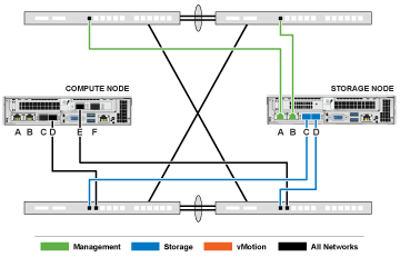
The following illustration shows the recommended cabling configuration for two-cable H410C compute nodes and four-cable H410S storage nodes. All switch ports in this example share the same configuration.
Example switch commands
You can use the following example commands to configure all switch ports used for NetApp HCI nodes. These commands are based on a Cisco configuration, but might require only small changes to apply to Mellanox switches. See your switch documentation for the specific commands you need to implement this configuration. Replace the interface name, description, and VLANs with the values for your environment.
interface {interface name, such as EthernetX/Y or GigabitEthernetX/Y/Z}
description {desired description, such as NetApp-HCI-NodeX-PortY}
mtu 9216
switchport mode trunk
switchport trunk native vlan 100
switchport trunk allowed vlan 105,107,200,201
spanning-tree port type edge trunk

|
Some switches might require inclusion of the native VLAN in the allowed VLAN list. See the documentation for your specific switch model and software version. |