

Replace DC power supply units in H615C and H610S nodes
 Suggest changes
H615C and H610S nodes support two –48 V to –60 V DC power supply units. These units are available as optional add-ons when you order H615C or H610S nodes. You can use the these instructions to remove the AC power supply units in the chassis and replace them with DC power supply units, or to replace a faulty DC power supply unit with a new DC power supply unit.
-
If you are replacing a faulty DC power supply unit, you have procured a replacement DC power supply unit.
-
If you are swapping out the AC power supply units in your chassis with DC units, you have taken into consideration the downtime for the procedure.
-
You have an electrostatic discharge (ESD) wristband, or you have taken other antistatic precautions.
-
You have ensured that the power supply requirements are met:
-
Supply voltage: –(48-60) V DC
-
Current consumption: 37A (maximum)
-
Breaker requirements: 40A breaker
-
-
You have ensured that the materials in your environment adhere to the RoHS specifications.
-
You have ensured that the cable requirements are met:
-
One UL 10 AWG, 2 m maximum (stranded) black cable [–(48-60) V DC]
-
One UL 10 AWG, 2 m maximum (stranded) red cable [V DC return]
-
One UL 10 AWG, 2 m maximum green/yellow cable, green with a yellow stripe, stranded wire (safety ground)
-
The procedure applies to the following node models:
-
One rack unit (1U) H615C compute chassis
-
1U H610S storage chassis

In the case of H615C and H610S, the terms "node" and "chassis" are used interchangeably because node and chassis are not separate components, unlike in the case of the 2U, four-node chassis.

|
You cannot mix AC and DC power supply units in your installation. |
-
Turn off the power supply units and unplug the power cords. If you are replacing a faulty DC power supply unit, turn off the power source and remove all the cables inserted into the blue connector.
-
Lift the cam handle, and press the blue latch to slide out the power supply unit.
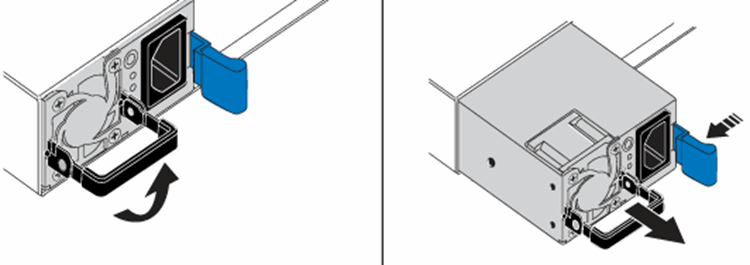
The illustration is an example. The location of the power supply unit in the chassis and the color of the release button vary depending on the type of chassis you have. 
Ensure that you use both hands to support the weight of the power supply unit. -
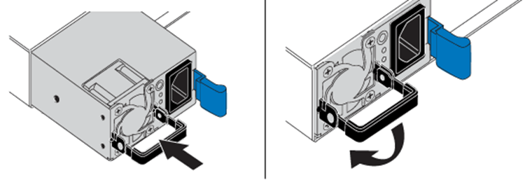
Using both hands, align the edges of the power supply unit with the opening in the chassis, gently push the unit into the chassis using the cam handle until it locks into place, and return the cam handle to the upright position.
-
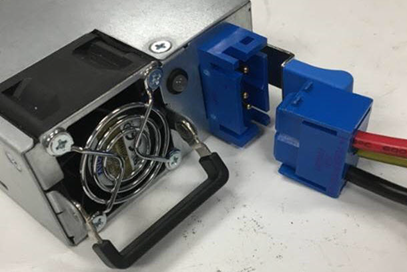
Cable the DC power supply units. Ensure that the power source is off while cabling the DC power supply unit and the power source.
-
Insert the black, red, and green/yellow cables to the blue connectors.
-
Insert the blue connector to the DC power supply units and the power source.
-
-
Power on the DC power supply units.

The power supply LEDs are lit when the DC power supply unit comes online. Green LED lights indicate that the power supply units are working correctly. -
Return the faulty unit to NetApp by following the instructions in the box that was shipped to you.