

Replace H410C nodes
 Suggest changes
You should replace a compute node in the event of CPU failure, other motherboard issues, or if it does not power on. The instructions apply to H410C nodes. If you have a H410C compute node that runs NetApp HCI Bootstrap OS version 1.6P1 or later, you do not have to replace the node if the memory DIMM fails; you need replace only the failed DIMM. If the DIMMs in your node have not failed, you can use them in the replacement node.

|
The replacement node should have the same version of NetApp HCI Bootstrap OS as the rest of the compute nodes in the NetApp HCI installation. NetApp recommends using the NetApp Deployment Engine to add a replacement compute node. If you cannot proceed with using the NetApp Deployment Engine for ESXi installation, see the NetApp Knowledge Base article How to install ESXi on NetApp HCI compute node manually. |
-
You have determined that the compute node needs to be replaced.
-
You have a replacement compute node.
To order a replacement node, you should contact NetApp Support. The compute node is shipped to you with the Bootstrap OS installed.
Nodes are shipped from the factory with the latest version of Bootstrap OS. You might need to perform the return to factory image (RTFI) process on the node in the following scenarios:-
Your current NetApp HCI installation is running a version of Bootstrap OS earlier than the latest version. In this case, the RTFI process will downgrade the new node to the OS version that your NetApp HCI installation is running.
-
The replacement node that is shipped is running a bootstrap OS version earlier than the latest version, and the NetApp HCI installation where the node is being replaced is already running the latest version. In this case, the RTFI process will upgrade the OS version on the new node to the latest version.
See How to RTFI using a USB key (login required) and How to RTFI by using the BMC (login required).
-
-
You have an electrostatic discharge (ESD) wristband, or you have taken other antistatic precautions.
-
You have labeled each cable that is connected to the compute node.
Alarms in the VMware vSphere Web Client alert you when a node fails. You should match the serial number of the failed node from the VMware vSphere Web Client with the serial number on the sticker at the back of the node.
When replacing an H410C compute node, consider the following:
-
You can intermix the H410C compute node with existing NetApp HCI compute and storage nodes in the same chassis and cluster.
-
The H410C compute node operates only on high-line voltage (200-240 VAC). You should ensure that the power requirements are met when you add H410C nodes to an existing NetApp HCI system.
Here is a high-level overview of the steps in this procedure:
Here are some additional tasks, which you might need to perform if your system has the specific conditions they are applicable to:
Step 1: Prepare to replace the compute node
You should migrate the virtual machines (VMs) hosted on the node to an available host, and remove the failed node from the cluster. You should get details about the failed node, such as serial number and networking information.
-
In the VMware vSphere Web Client, perform the steps to migrate the VMs to another available host.
See the VMware documentation for the migration steps. -
Perform the steps to remove the node from the inventory. The steps depend on the version of NetApp HCI in your current installation:
NetApp HCI version number Steps NetApp HCI 1.3 and later
-
Select the failed node, and select Monitor > Hardware Status > Sensors.
-
Note the serial number of the failed node.
This helps you identify the node in the chassis by matching the serial number on the sticker at the back of the node with the serial number you noted. -
Right-click the failed node and select Connection > Disconnect.
-
Select Yes to confirm the action.
-
Right-click the failed node and select Remove from Inventory.
-
Select Yes to confirm the action.
NetApp HCI versions earlier than 1.3
-
Right-click the node and select Remove from Inventory.
-
Select the failed node, and select Monitor > Hardware Status > Sensors.
-
Note the Node 0 serial number, which is the serial number of the failed node. This helps you identify the node in the chassis by matching the serial number on the sticker at the back of the node with the serial number you noted.
-
With the failed node selected, select Manage > Networking > VMkernel adapters, and copy the four IP addresses listed.
You can reuse this information when you perform the initial network configuration steps in VMware ESXi.
-
Step 2: Replace the compute node in the chassis
After you remove the failed node from the cluster, you can remove the node from the chassis, and install the replacement node.
|
|
Ensure that you have antistatic protection before you perform the steps here. |
-
Put on antistatic protection.
-
Unpack the new node, and set it on a level surface near the chassis.
Keep the packaging material for when you return the failed node to NetApp. -
Label each cable that is inserted at the back of the node that you want to remove.
After you install the new node, you should insert the cables back into the original ports. -
Disconnect all the cables from the node.
-
If you want to reuse the DIMMs, remove them.
-
Pull down the cam handle on the right side of the node, and pull the node out using both the cam handles.
The cam handle that you should pull down has an arrow on it to indicate the direction in which it moves. The other cam handle does not move and is there to help you pull the node out.
Support the node with both your hands when you pull it out of the chassis. -
Place the node on a level surface.
You should package the node and return it to NetApp. -
Install the replacement node.
-
Push the node in until you hear a click.

Ensure that you do not use excessive force when sliding the node into the chassis.
Ensure that the node powers on. If it does not power on automatically, push the power button at the front of the node. -
If you removed DIMMs from the failed node earlier, insert them into the replacement node.
You should replace DIMMs in the same slots they were removed from in the failed node. -
Reconnect the cables to the ports from which you originally disconnected them.
The labels you had attached to the cables when you disconnected them help guide you.
If the airflow vents at the rear of the chassis are blocked by cables or labels, it can lead to premature component failures due to overheating.
Do not force the cables into the ports; you might damage the cables, ports, or both.
Ensure that the replacement node is cabled in the same way as the other nodes in the chassis. -
Configure your BMC, see Configure IPMI for each node for details.
-
See the NetApp Knowledge Base article How to disable BMC web UI access on HCI and SolidFire H-Series systems to determine if your BMC web access needs to be disabled.
Step 3: Remove the compute node asset in NetApp HCI 1.7 and later
In NetApp HCI 1.7 and later, after you physically replace the node, you should remove the compute node asset using the management node APIs. To use REST APIs, your storage cluster must be running NetApp Element software 11.5 or later and you should have deployed a management node running version 11.5 or later.
-
Enter the management node IP address followed by /mnode:
https://[IP address]/mnode -
Select Authorize or any lock icon and enter cluster admin credentials for permissions to use APIs.
-
Enter the cluster user name and password.
-
Select Request body from the type drop-down list if the value is not already selected.
-
Enter the client ID as mnode-client if the value is not already populated.
Do not enter a value for the client secret. -
Select Authorize to begin a session.
If you get the Auth Error TypeError: Failed to fetcherror message after you attempt to authorize, you might need to accept the SSL certificate for the MVIP of your cluster. Copy the IP in the Token URL, paste the IP into another browser tab, and authorize again. If you attempt to run a command after the token expires, you get aError: UNAUTHORIZEDerror. If you receive this response, authorize again.
-
-
Close the Available authorizations dialog box.
-
Select GET/assets.
-
Select Try it out.
-
Select Execute.
Scroll down in the response body to the Compute section, and copy the parent and id values for the failed compute node. -
Select DELETE/assets/{asset_id}/compute-nodes/{compute_id}.
-
Select Try it out.
Enter the parent and id values you got in step 7. -
Select Execute.
Step 4: Add the compute node to the cluster
You should add the compute node back to the cluster. The steps vary depending on the version of NetApp HCI you are running.
NetApp HCI 1.6P1 and later
You can use NetApp Hybrid Cloud Control only if your NetApp HCI installation runs on version 1.6P1 or later.
-
Ensure that the vSphere instance NetApp HCI is using has vSphere Enterprise Plus licensing if you are expanding a deployment with Virtual Distributed Switches.
-
Ensure that none of the vCenter or vSphere instances in use with NetApp HCI have expired licenses.
-
Ensure that you have free and unused IPv4 addresses on the same network segment as existing nodes (each new node must be installed on the same network as existing nodes of its type).
-
Ensure that you have the vCenter administrator account credentials ready.
-
Ensure that each new node uses the same network topology and cabling as the existing storage or compute clusters.
-
Manage the initiators and volume access groups for the new compute node.
-
Open the IP address of the management node in a web browser. For example:
https://<ManagementNodeIP>
-
Log in to NetApp Hybrid Cloud Control by providing the NetApp HCI storage cluster administrator credentials.
-
In the Expand Installation pane, select Expand.
-
Log in to the NetApp Deployment Engine by providing the local NetApp HCI storage cluster administrator credentials.
You cannot log in using Lightweight Directory Access Protocol credentials. -
On the Welcome page, select Yes.
-
On the End User License page, perform the following actions:
-
Read the VMware End User License Agreement.
-
If you accept the terms, select I accept at the end of the agreement text.
-
-
Select Continue.
-
On the vCenter page, perform the following steps:
-
Enter a FQDN or IP address and administrator credentials for the vCenter instance associated with your NetApp HCI installation.
-
Select Continue.
-
Select an existing vSphere datacenter to which to add the new compute node, or select Create New Datacenter to add the new compute nodes to a new datacenter.
If you select Create New Datacenter, the Cluster field is automatically populated. -
If you selected an existing datacenter, select a vSphere cluster with which the new compute nodes should be associated.
If NetApp HCI cannot recognize the network settings of the cluster you have selected, ensure that the vmkernel and vmnic mapping for the management, storage, and vMotion networks are set to the deployment defaults. -
Select Continue.
-
-
On the ESXi Credentials page, enter an ESXi root password for the compute node or nodes you are adding.
You should use the same password that was created during the initial NetApp HCI deployment. -
Select Continue.
-
If you created a new vSphere datacenter cluster, on the Network Topology page, select a network topology to match the new compute nodes you are adding.
You can only select the two-cable option if your compute nodes are using the two-cable topology and the existing NetApp HCI deployment is configured with VLAN IDs. -
On the Available Inventory page, select the node you want to add to the existing NetApp HCI installation.
For some compute nodes, you might need to enable EVC at the highest level your vCenter version supports before you can add them to your installation. You should use the vSphere client to enable EVC for these compute nodes. After you enable it, refresh the Inventory page and try adding the compute nodes again. -
Select Continue.
-
Optional: If you created a new vSphere datacenter cluster, on the Network Settings page, import network information from an existing NetApp HCI deployment by selecting the Copy Setting from an Existing Cluster checkbox.
This populates the default gateway and subnet information for each network. -
On the Network Settings page, some of the network information has been detected from the initial deployment. The new compute node is listed by serial number, and you should assign new network information to it. For the new compute node, perform the following steps:
-
If NetApp HCI detected a naming prefix, copy it from the Detected Naming Prefix field, and insert it as the prefix for the new unique hostname you add in the Hostname field.
-
In the Management IP Address field, enter a management IP address for the compute node that is within the management network subnet.
-
In the vMotion IP Address field, enter a vMotion IP address for the compute node that is within the vMotion network subnet.
-
In the iSCSI A - IP Address field, enter an IP address for the first iSCSI port of the compute node that is within the iSCSI network subnet.
-
In the iSCSI B - IP Address field, enter an IP address for the second iSCSI port of the compute node that is within the iSCSI network subnet.
-
-
Select Continue.
-
On the Review page in the Network Settings section, the new node is shown in bold text. If you need to make changes to the information in any section, perform the following steps:
-
Select Edit for that section.
-
When finished making changes, click Continue on any subsequent pages to return to the Review page.
-
-
Optional: If you do not want to send cluster statistics and support information to NetApp-hosted SolidFire Active IQ servers, clear the final checkbox.
This disables real-time health and diagnostic monitoring for NetApp HCI. Disabling this feature removes the ability for NetApp to proactively support and monitor NetApp HCI to detect and resolve problems before production is affected. -
Select Add Nodes.
You can monitor the progress while NetApp HCI adds and configures the resources. -
Optional: Verify that the new compute node is visible in vCenter.
NetApp HCI 1.4 P2, 1.4, and 1.3
If your NetApp HCI installation runs version 1.4P2, 1.4, or 1.3, you can use the NetApp Deployment Engine to add the node to the cluster.
-
Ensure that the vSphere instance NetApp HCI is using has vSphere Enterprise Plus licensing if you are expanding a deployment with Virtual Distributed Switches.
-
Ensure that none of the vCenter or vSphere instances in use with NetApp HCI have expired licenses.
-
Ensure that you have free and unused IPv4 addresses on the same network segment as existing nodes (each new node must be installed on the same network as existing nodes of its type).
-
Ensure that you have the vCenter administrator account credentials ready.
-
Ensure that each new node uses the same network topology and cabling as the existing storage or compute clusters.
-
Browse to the management IP address of one of the existing storage nodes:
http://<storage_node_management_IP_address>/ -
Log in to the NetApp Deployment Engine by providing the local NetApp HCI storage cluster administrator credentials.
You cannot log in using Lightweight Directory Access Protocol credentials. -
Select Expand Your Installation.
-
On the Welcome page, select Yes.
-
On the End User License page, perform the following actions:
-
Read the VMware End User License Agreement.
-
If you accept the terms, select I accept at the end of the agreement text.
-
-
Select Continue.
-
On the vCenter page, perform the following steps:
-
Enter a FQDN or IP address and administrator credentials for the vCenter instance associated with your NetApp HCI installation.
-
Select Continue.
-
Select an existing vSphere datacenter to which to add the new compute node.
-
Select a vSphere cluster with which the new compute node should be associated.
If you are adding a compute node with a CPU generation that is different than the CPU generation of the existing compute nodes and Enhanced vMotion Compatibility (EVC) is disabled on the controlling vCenter instance, you should enable EVC before proceeding. This ensures vMotion functionality after expansion is complete. -
Select Continue.
-
-
On the ESXi Credentials page, create ESXi administrator credentials for the compute node you are adding.
You should use the same master credentials that were created during the initial NetApp HCI deployment. -
Select Continue.
-
On the Available Inventory page, select the node you want to add to the existing NetApp HCI installation.
For some compute nodes, you might need to enable EVC at the highest level your vCenter version supports before you can add them to your installation. You should use the vSphere client to enable EVC for these compute nodes. After you enable it, refresh the Inventory page and try adding the compute nodes again. -
Select Continue.
-
On the Network Settings page, perform the following steps:
-
Verify the information detected from the initial deployment.
-
Each new compute node is listed by serial number, and you should assign new network information to it. For each new storage node, perform the following steps:
-
If NetApp HCI detected a naming prefix, copy it from the Detected Naming Prefix field, and insert it as the prefix for the new unique hostname you add in the Hostname field.
-
In the Management IP Address field, enter a management IP address for the compute node that is within the management network subnet.
-
In the vMotion IP Address field, enter a vMotion IP address for the compute node that is within the vMotion network subnet.
-
In the iSCSI A - IP Address field, enter an IP address for the first iSCSI port of the compute node that is within the iSCSI network subnet.
-
In the iSCSI B - IP Address field, enter an IP address for the second iSCSI port of the compute node that is within the iSCSI network subnet.
-
-
Select Continue.
-
-
On the Review page in the Network Settings section, the new node is shown in bold text. If you want to make changes to information in any section, perform the following steps:
-
Select Edit for that section.
-
When finished making changes, select Continue on any subsequent pages to return to the Review page.
-
-
Optional: If you do not want to send cluster statistics and support information to NetApp-hosted Active IQ servers, clear the final checkbox.
This disables real-time health and diagnostic monitoring for NetApp HCI. Disabling this feature removes the ability for NetApp to proactively support and monitor NetApp HCI to detect and resolve problems before production is affected. -
Select Add Nodes.
You can monitor the progress while NetApp HCI adds and configures the resources. -
Optional: Verify that the new compute node is visible in vCenter.
NetApp HCI 1.2, 1.1, and 1.0
After you physically replace the node, you should add it back to the VMware ESXi cluster and perform several networking configurations so that you can use all the available functionalities.
|
|
You should have a console or keyboard, video, mouse (KVM) to perform these steps. |
-
Install and configure VMware ESXi version 6.0.0 as follows:
-
On the remote console or KVM screen, select Power Control > Set Power Reset.
This restarts the node. -
In the Boot Menu window that opens, select ESXi Install by pressing the Down Arrow key.
This window stays open for only five seconds. If you do not make the selection in five seconds, you should restart the node again. -
Press Enter to start the installation process.
-
Complete the steps in the installation wizard.
When asked to select the disk to install ESXi on, you should select the second disk drive in the list by selecting the Down Arrow key. When asked to enter a root password, you should enter the same password that you configured in the NetApp Deployment Engine when you set up NetApp HCI. -
After the installation is complete, press Enter to restart the node.
By default, the node restarts with the NetApp HCI Bootstrap OS. You should perform a one-time configuration on the node for it to use VMware ESXi.
-
-
Configure VMware ESXi on the node as follows:
-
In the NetApp HCI Bootstrap OS terminal user interface (TUI) login window, enter the following information:
-
User name: element
-
Password: catchTheFire!
-
-
Press the Down Arrow key to select OK.
-
Press Enter to log in.
-
In the main menu, use the Down Arrow key to select Support Tunnel > Open Support Tunnel.
-
In the window that is displayed, enter the port information.
You should contact NetApp Support for this information. NetApp Support logs in to the node to set the boot configuration file and complete the configuration task. -
Restart the node.
-
-
Configure the management network as follows:
-
Log in to VMware ESXi by entering the following credentials:
-
User name: root
-
Password: The password you set when you installed VMware ESXi.
The password should match what you configured in the NetApp Deployment Engine when you set up NetApp HCI.
-
-
Select Configure Management Network, and press Enter.
-
Select Network Adapters, and press Enter.
-
Select vmnic2 and vmnic3, and press Enter.
-
Select IPv4 Configuration, and press the Spacebar on the keyboard to select the static configuration option.
-
Enter the IP address, subnet mask, and default gateway information, and press Enter.
You can reuse the information that you copied before you removed the node. The IP address you enter here is the Management Network IP address that you copied earlier. -
Press Esc to exit the Configure Management Network section.
-
Select Yes to apply the changes.
-
-
Configure networking so that the node is synchronized with the other nodes in the cluster as follows:
Element Plug-in for vCenter 5.0 and laterBeginning with Element Plug-in for vCenter 5.0, add the node (host) to the datacenter.
-
In the VMware vSphere Web Client, select Inventory > Hosts and Clusters.
-
Right-click on the datacenter, and select Add Host.
The wizard guides you through adding the host.
When you are asked to enter the user name and password, use the following credentials:
User name: root
Password: The password you configured in the NetApp Deployment Engine when you set up NetApp HCIIt might take a few minutes for the node to get added to the cluster. After the process is complete, the newly added node is listed under the cluster.
-
Select the node, and then select Configure > Networking > Virtual switches, and perform the following steps:
-
Expand vSwitch0.
-
In the graphic that is displayed, select the VM Network
 icon followed by Remove.
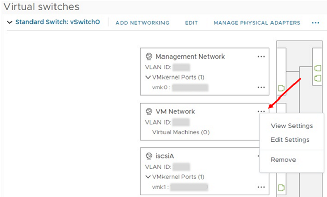
-
Confirm the action.
-
Select EDIT on the vSwitch0 header.
-
In the vSwitch0 - Edit settings window, select Teaming and failover.
-
Verify that vmnic3 is listed under Standby adapters, and select OK.
-
-
In the graphic that is displayed, select the Management Network
icon followed by Edit Settings.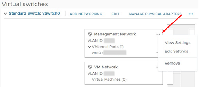
-
In the Management Network - Edit settings window, select Teaming and failover.
-
Verify that vmnic3 is listed under Standby adapters, and select OK.
-
-
Select Add Networking on the vSwitch0 header, and enter the following details in the window that is displayed:
-
For connection type, select Virtual Machine Port Group for a Standard Switch, and select Next.
-
For target device, select New standard switch, and select Next.
-
Under Create a Standard Switch, move vmnic0 and vmnic4 to Active adapters, and select Next.
-
Under connection settings, verify that VM Network is the network label and, if required, enter the VLAN ID.
-
Select Next.
-
Review the Ready to complete screen, and select Finish.
-
-
Expand vSwitch1 and select EDIT to edit the settings as follows:
-
Under Properties, set MTU to 9000, and select OK.
-
-
In the graphic that is displayed, select the VM Network
icon followed by Edit.-
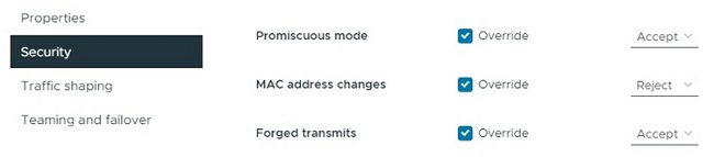
Select Security, and make the following selections:
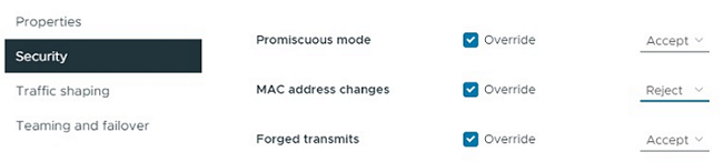
-
Select Teaming and failover, and select the Override checkbox.
-
Move vmnic0 to Standby adapters.
-
Select OK.
-
-
Select ADD NETWORKING on the vSwitch1 header and enter the following details in the Add Networking window:
-
For connection type, select VMkernel Network Adapter, and select Next.
-
For target device, select the option to use an existing standard switch, browse to vSwitch1, and select Next.
-
Under Create a Standard Switch, move vmnic1 and vmnic5 to Active adapters, and select Next.
-
Under port properties, change the network label to vMotion, select the checkbox for vMotion traffic under Enable services, and select Next.
-
Under IPv4 settings, provide the IPv4 information, and select Next.
-
If you are ready to proceed, select Finish.
-
-
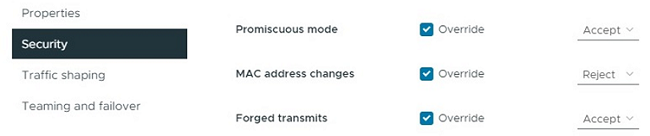
In the graphic that is displayed, select the vMotion
icon followed by Edit.-
Select Security, and make the following selections:

-
Select Teaming and failover, and select the Override checkbox.
-
Move vmnic4 to Standby adapters.
-
Select OK.
-
-
Select ADD NETWORKING on the vSwitch1 header and enter the following details in the Add Networking window:
-
For connection type, select VMkernel Network Adapter, and select Next.
-
For target device, select New standard switch, and select Next.
-
Under Create a Standard Switch, move vmnic1 and vmnic5 to Active adapters, and select Next.
-
Under port properties, change the network label to iSCSI-B, and select Next.
-
Under IPv4 settings, provide the IPv4 information, and select Next.
-
If you are ready to proceed, select Finish.
-
-
Expand vSwitch2, and select EDIT:
-
Under Properties, set MTU to 9000, and select OK.
-
-
In the graphic that is displayed, select the iSCSI-B
icon followed by Edit.-
Select Security, and make the following selections:
-
Select Teaming and failover, and select the Override checkbox.
-
Move vmnic1 to Unused adapters.
-
Select OK.
-
-
Select ADD NETWORKING on the vSwitch1 header and enter the following details in the Add Networking window:
-
For connection type, select VMkernel Network Adapter, and select Next.
-
For target device, select the option to use an existing standard switch, browse to vSwitch2, and select Next.
-
Under port properties, change the network label to iSCSI-A, and select Next.
-
Under IPv4 settings, provide the IPv4 information, and select Next.
-
If you are ready to proceed, select Finish.
-
-
In the graphic that is displayed, select the iSCSI-A
icon followed by Edit.-
Select Security, and make the following selections:
-
Select Teaming and failover, and select the Override checkbox.
-
Move vmnic5 to Unused adapters by using the arrow icon.
-
Select OK.
-
-
With the newly added node selected and the Configure tab open, select Storage > Storage Adapters, and perform the following steps:
-
Select the ADD SOFTWARE ADAPTER list.
-
Select Add iSCSI adapter, and select OK.
-
Under Storage Adapters, select the iSCSI adapter
-
Under Properties > General, copy the iSCSI Name.
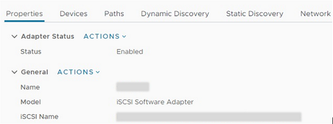
You need the iSCSI Name when you create the initiator.
-
-
Perform the following steps in the NetApp SolidFire vCenter Plug-in:
-
Select the target instance.
-
Select Management.
-
Select the target cluster.
-
Select Management > Initiators.
-
Select Create Initiator.
-
Enter the IQN address you copied earlier in the IQN/WWPN field.
-
Select OK.
-
Select the new initiator.
-
Select Actions list > Bulk Actions, and select Add to Access Group.
-
Select the target access group, and select Add.
-
-
In the VMware vSphere Web Client, under Storage Adapters, select the iSCSI adapter, and perform the following steps:
-
Select Dynamic Discovery > Add.
-
Enter the SVIP IP address in the iSCSI Server field.
To get the SVIP IP address, select NetApp Element Management, and copy the SVIP IP address.
Leave the default port number as is. It should be 3260. -
Select OK.
-
Select Network Port Binding, and select ADD.
-
Select iSCSI-A and iSCSI-B, and Select OK
-
Select RESCAN ADAPTER.
-
Select RESCAN STORAGE. Scan for new VMFS Volumes and select OK.
-
After the rescan is complete, verify if the volumes in the cluster and datastores are visible on the new compute node (host).
-
Element Plug-in for vCenter 4.10 and earlierFor Element Plug-in for vCenter 4.10 and earlier, add the node (host) to the cluster.
-
In the VMware vSphere Web Client, select Hosts and Clusters.
-
Right-click the cluster that you want to add the node to, and select Add Host.
The wizard guides you through adding the host.
When you are asked to enter the user name and password, use the following credentials:
User name: root
Password: The password you configured in the NetApp Deployment Engine when you set up NetApp HCIIt might take a few minutes for the node to get added to the cluster. After the process is complete, the newly added node is listed under the cluster.
-
Select the node, and then select Manage > Networking > Virtual switches, and perform the following steps:
-
Select vSwitch0.
You should see only vSwitch0 listed in the table that is displayed. -
In the graphic that is displayed, select VM Network, and click X to remove the VM Network port group.
-
Confirm the action.
-
Select vSwitch0, and then select the pencil icon to edit the settings.
-
In the vSwitch0 - Edit settings window, select Teaming and failover.
-
Ensure that vmnic3 is listed under Standby adapters, and select OK.
-
In the graphic that is displayed, select Management Network, and select the pencil icon to edit the settings.
-
In the Management Network - Edit settings window, select Teaming and failover.
-
Move vmnic3 to Standby adapters by using the arrow icon, and select OK.
-
-
From the Actions drop-down menu, select Add Networking, and enter the following details in the window that is displayed:
-
For connection type, select Virtual Machine Port Group for a Standard Switch, and select Next.
-
For target device, select the option to add a new standard switch, and select Next.
-
Select +.
-
In the Add Physical Adapters to Switch window, select vmnic0 and vmnic4, and select OK.
vmnic0 and vmnic4 are now listed under Active adapters. -
Select Next.
-
Under connection settings, verify that VM Network is the network label, and select Next.
-
If you are ready to proceed, select Finish.
vSwitch1 is displayed in the list of virtual switches.
-
-
Select vSwitch1, and select the pencil icon to edit the settings as follows:
-
Under Properties, set MTU to 9000, and select OK.
In the graphic that is displayed, select VM Network, and click the pencil icon to edit the settings as follows:
-
-
Select Security, and make the following selections:
-
Select Teaming and failover, and select the Override checkbox.
-
Move vmnic0 to Standby adapters by using the arrow icon.
-
Select OK.
-
-
With vSwitch1 selected, from the Actions drop-down menu, select Add Networking, and enter the following details in the window that is displayed:
-
For connection type, select VMkernel Network Adapter, and select Next.
-
For target device, select the option to use an existing standard switch, browse to vSwitch1, and select Next.
-
Under port properties, change the network label to vMotion, select the checkbox for vMotion traffic under Enable services, and select Next.
-
Under IPv4 settings, provide the IPv4 information, and select Next.
The IP address you enter here is the vMotion IP address that you copied earlier. -
If you are ready to proceed, select Finish.
-
-
In the graphic that is displayed, select vMotion, and select the pencil icon to edit the settings as follows:
-
Select Security, and make the following selections:

-
Select Teaming and failover, and select the Override checkbox.
-
Move vmnic4 to Standby adapters by using the arrow icon.
-
Select OK.
-
-
With vSwitch1 selected, from the Actions drop-down menu, select Add Networking and enter the following details in the window that is displayed:
-
For connection type, select VMkernel Network Adapter, and select Next.
-
For target device, select the option to add a new standard switch, and select Next.
-
Select +.
-
In the Add Physical Adapters to Switch window, select vmnic1 and vmnic5, and select OK.
vmnic1 and vmnic5 are now listed under Active adapters. -
Select Next.
-
Under port properties, change the network label to iSCSI-B, and select Next.
-
Under IPv4 settings, provide the IPv4 information, and select Next.
The IP address you enter here is the iSCSI-B IP address that you copied earlier. -
If you are ready to proceed, select Finish.
vSwitch2 is displayed in the list of virtual switches.
-
-
Select vSwitch2, and select the pencil icon to edit the settings as follows:
-
Under Properties, set MTU to 9000, and select OK.
-
-
In the graphic that is displayed, select iSCSI-B, and select the pencil icon to edit the settings as follows:
-
Select Security, and make the following selections:

-
Select Teaming and failover, and select the Override checkbox.
-
Move vmnic1 to Unused adapters by using the arrow icon.
-
Select OK.
-
-
From the Actions drop-down menu, select Add Networking and enter the following details in the window that is displayed:
-
For connection type, select VMkernel Network Adapter, and select Next.
-
For target device, select the option to use an existing standard switch, browse to vSwitch2, and select Next.
-
Under port properties, change the network label to iSCSI-A, and select Next.
-
Under IPv4 settings, provide the IPv4 information, and select Next.
The IP address you enter here is the iSCSI-A IP address that you copied earlier. -
If you are ready to proceed, select Finish.
-
-
In the graphic that is displayed, select iSCSI-A, and select the pencil icon to edit the settings as follows:
-
Select Security, and make the following selections:

-
Select Teaming and failover, and select the Override checkbox.
-
Move vmnic5 to Unused adapters by using the arrow icon.
-
Select OK.
-
-
With the newly added node selected and the Manage tab open, select Storage > Storage Adapters, and perform the following steps:
-
Select + and select Software iSCSI Adapter.
-
To add the iSCSI adapter, select OK in the dialog box.
-
Under Storage Adapters, select the iSCSI adapter, and from the Properties tab, copy the iSCSI Name.
You need the iSCSI Name when you create the initiator.
-
-
Perform the following steps in the NetApp SolidFire vCenter Plug-in:
-
Select Management > Initiators > Create.
-
Select Create a Single Initiator.
-
Enter the IQN address you copied earlier in the IQN/WWPN field.
-
Select OK.
-
Select Bulk Actions, and select Add to Volume Access Group.
-
Select NetApp HCI, and select Add.
-
-
In the VMware vSphere Web Client, under Storage Adapters, select the iSCSI adapter, and perform the following steps:
-
Under Adapter Details, select Targets > Dynamic Discovery > Add.
-
Enter the SVIP IP address in the iSCSI Server field.
To get the SVIP IP address, select NetApp Element Management, and copy the SVIP IP address.
Leave the default port number as is. It should be 3260. -
Select OK.
A message recommending a rescan of the storage adapter is displayed. -
Select the rescan icon.
-
Under Adapter Details, select Network Port Binding, and select +.
-
Select the check boxes for iSCSI-B and iSCSI-A, and click OK.
A message recommending a rescan of the storage adapter is displayed. -
Select the rescan icon.
After the rescan is complete, verify if the volumes in the cluster are visible on the new compute node (host).
-
-
Step 5: Redeploy Witness Nodes for two and three-node storage clusters
After you physically replace the failed compute node, you should redeploy the NetApp HCI Witness Node VM if the failed compute node was hosting the Witness Node. These instructions apply only to compute nodes that are part of a NetApp HCI installation with two or three-node storage clusters.
-
Gather the following information:
-
Cluster name from the storage cluster
-
Subnet mask, gateway IP address, DNS server, and domain information for the management network
-
Subnet mask for the storage network
-
-
Ensure that you have access to the storage cluster to be able to add the Witness Nodes to the cluster.
-
Consider the following conditions to help you decide whether to remove the existing Witness Node from VMware vSphere Web Client or the storage cluster:
-
If you want to use the same VM name for the new Witness Node, you should delete all the references to the old Witness Node from vSphere.
-
If you want to use the same host name on the new Witness Node, you should first remove the old Witness Node from the storage cluster.
You cannot remove the old Witness Node if your cluster is down to only two physical storage nodes (and no Witness Nodes). In this scenario, you should add the new Witness Node to the cluster first before removing the old one.
You can remove the Witness Node from the cluster using the NetApp Element Management extension point.
-
You should redeploy Witness Nodes in the following scenarios:
-
You replaced a failed compute node that is part of a NetApp HCI installation, which has a two or three-node storage cluster and the failed compute node was hosting a Witness Node VM.
-
You performed the return to factory image (RTFI) procedure on the compute node.
-
The Witness Node VM is corrupted.
-
The Witness Node VM was accidentally removed from ESXi.
The VM is configured using the template that is created as part of initial deployment using the NetApp Deployment Engine. Here is an example of what a Witness Node VM looks like: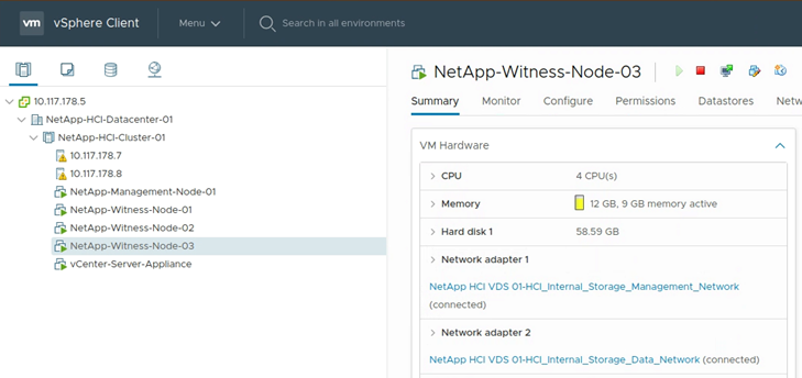
|
|
If you deleted the VM template, you should contact NetApp Support to get the Witness Node .ova image and redeploy it. You can download the template from here (login required). However, you should engage Support for guidance with setting it up. |
-
In the VMware vSphere Web Client, select Hosts and Clusters.
-
Right-click the compute node that will host the Witness Node VM, and select New Virtual Machine.
-
Select Deploy from template, and select Next.
-
Follow the steps in the wizard:
-
Select Data Center, locate the VM template, and select Next.
-
Enter a name for the VM in the following format: NetApp-Witness-Node-##
## should be replaced with a number. -
Leave the default selection for VM location as is, and select Next.
-
Leave the default selection for the destination compute resource as is, and select Next.
-
Select the local datastore, and select Next.
Free space on the local datastore varies depending on the compute platform. -
Select Power on virtual machine after creation from the list of deploy options, and select Next.
-
Review the selections, and select Finish.
-
-
Configure the management and storage network, and cluster settings for the Witness Node as follows:
-
In the VMware vSphere Web Client, select Hosts and Clusters.
-
Right-click the Witness Node, and power it on if it is not already powered on.
-
In the Summary view of the Witness Node, select Launch Web Console.
-
Wait for the Witness Node to boot up to the menu with the blue background.
-
Select anywhere inside the console to access the menu.
-
Configure the management network as follows:
-
Press the down arrow key to navigate to Network, and then press Enter for OK.
-
Navigate to Network config, and then press Enter for OK.
-
Navigate to net0, and then press Enter for OK.
-
Press Tab till you get to the IPv4 field, and then if applicable, delete the existing IP in the field and enter the management IP information for the Witness Node. Check the subnet mask and gateway as well.
No VLAN tagging will be applied at the VM host level; tagging will be handled in vSwitch. -
Press Tab to navigate to OK, and press Enter to save changes.
After management network configuration, the screen returns to Network.
-
-
Configure the storage network as follows:
-
Press the down arrow key to navigate to Network, and then press Enter for OK.
-
Navigate to Network config, and then press Enter for OK.
-
Navigate to net1, and then press Enter for OK.
-
Press Tab till you get to the IPv4 field, and then if applicable, delete the existing IP in the field and enter the storage IP information for the Witness Node.
-
Press Tab to navigate to OK, and press Enter to save the changes.
-
Set MTU to 9000.
If MTU is not set before you add the Witness Node to the cluster, you see cluster warnings for inconsistent MTU settings. This can prevent garbage collection from running and cause performance problems. -
Press Tab to navigate to OK, and press Enter to save changes.
After storage network configuration, the screen returns to Network.
-
-
Configure the cluster settings as follows:
-
Press Tab to navigate to Cancel, and press Enter.
-
Navigate to Cluster settings, and then press Enter for OK.
-
Press Tab to navigate to Change Settings, and press Enter for Change Settings.
-
Press Tab to navigate to Hostname field, and enter the host name.
-
Press the down arrow key to access the Cluster field and enter the cluster name from the storage cluster.
-
Press the Tab key to navigate to OK button, and press Enter.
-
-
-
Add the Witness Node to the storage cluster as follows:
-
From the vSphere Web Client, access the NetApp Element Management extension point from the Shortcuts tab or the side panel.
-
Select NetApp Element Management > Cluster.
-
Select the Nodes sub-tab.
-
Select Pending from the drop-down list to view the list of nodes.
The Witness Node should appear in the pending nodes list. -
Select the check box for the node you want to add, and select Add node.
When the action is complete, the node appears in the list of active nodes for the cluster.
-
Change the password if you received a replacement node with a non-standard BMC password
Some replacement nodes may be shipped with non-standard passwords for the baseboard management controller (BMC) UI. If you receive a replacement node with a non-standard BMC password, you should change the password to the default, ADMIN.
-
Identify whether you received a replacement node with a non-standard BMC password:
-
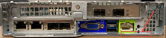
Look for a sticker under the IPMI port at the back of the replacement node that you received. If you locate a sticker under the IPMI port, it means that you received a node with a non-standard BMC password. See the following sample image:
-
Make a note of the password.
-
-
Log in to the BMC UI using the unique password found on the sticker.
-
Select Factory Default, and select the Remove current settings and set the user defaults to ADMIN/ADMIN radio button:
-
Select Restore.
-
Log out and then log back in to confirm that the credentials are now changed.
Upgrade the firmware on your node
After you replace the compute node, you might have to upgrade the firmware version. See Upgrade compute node firmware for details.