

Replace SN2010, SN2100, and SN2700 switches
 Suggest changes
You can replace a faulty SN2000 series switch non-disruptively by following the best practices and steps provided by NetApp.
-
Ensure that Putty is installed on the laptop and that you capture the output. See this video to learn how to configure Putty to capture the output session.
-
Ensure that you run NetApp Config Advisor before and after the replacement. This can help identify other problems before the maintenance starts. Download and install Config Advisor, and access the Quick Start Guide from here (login required).
-
Obtain a power cable, the basic hand tools, and labels.
-
Ensure that you have planned for a two to four-hour maintenance window.
-
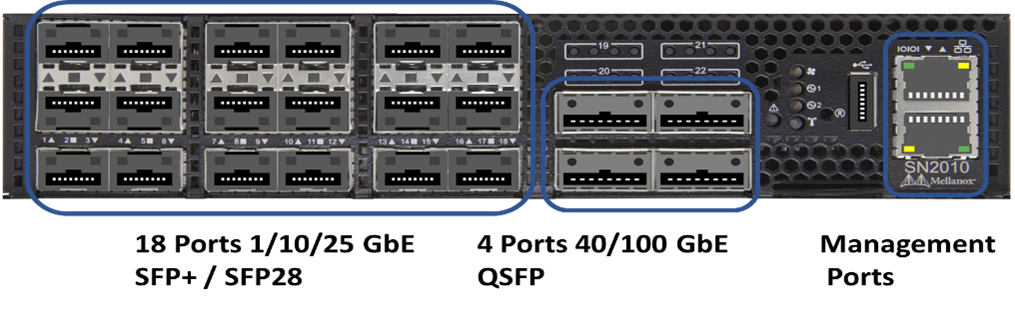
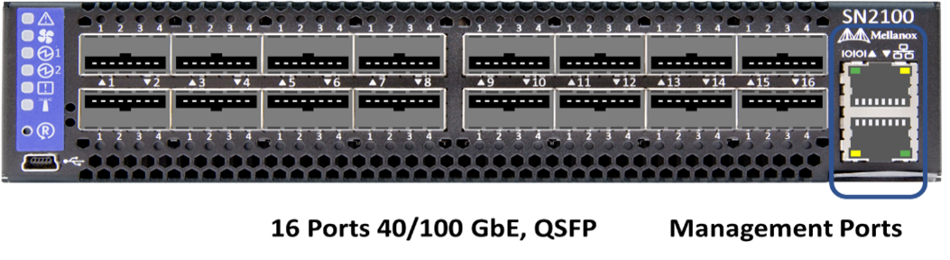
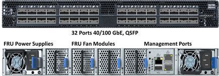
Familiarize yourself with the switch ports below:
You should perform the steps in this procedure in the order below. This is to ensure that the downtime is minimal and the replacement switch is pre-configured before the switch replacement.

|
Contact NetApp Support if you need guidance. |
Here is an overview of the steps in the procedure:
Prepare to replace the faulty switch
Perform the following steps before you replace the faulty switch.
-
Verify that the replacement switch is the same model as the faulty switch.
-
Label all the cables connected to the faulty switch.
-
Identify the external file server where the switch configuration files are saved.
-
Ensure that you have obtained the following information:
-
The interface used for the initial configuration: RJ-45 port or the Serial Terminal Interface.
-
The credentials needed for switch access: IP address of the management port of the non-faulty switch and the faulty switch.
-
The passwords for administration access.
-
Create the configuration file
You can configure a switch by using the configuration files you create. Choose from one of the following options to create the configuration file for the switch.
| Option | Steps |
|---|---|
Create the backup configuration file from the faulty switch |
|
Create the backup configuration file by modifying the file from another switch |
|
Remove the faulty switch and install the replacement
Perform the steps to remove the faulty switch and the install the replacement.
-
Locate the power cables on the faulty switch.
-
Label and unplug the power cables after the switch reboots.
-
Label and unplug all the cables from the faulty switch and secure them to prevent damage during switch replacement.
-
Remove the switch from the rack.
-
Install the replacement switch in the rack.
-
Connect the power cables and management port cables.
The switch automatically powers on when AC power is applied. There is no power button. It might take up to five minutes for the System Status LED to turn green. -
Connect to the switch using the RJ-45 management port or the Serial Terminal Interface.
Verify the operating system version on the switch
Verify the OS software version on the switch. The version on the faulty switch and the healthy switch should match.
-
Connect to your switch remotely using SSH.
-
Enter Configuration mode.
-
Run the
show versioncommand. See the following example:SFPS-HCI-SW02-A (config) #show version Product name: Onyx Product release: 3.7.1134 Build ID: #1-dev Build date: 2019-01-24 13:38:57 Target arch: x86_64 Target hw: x86_64 Built by: jenkins@e4f385ab3f49 Version summary: X86_64 3.7.1134 2019-01-24 13:38:57 x86_64 Product model: x86onie Host ID: 506B4B3238F8 System serial num: MT1812X24570 System UUID: 27fe4e7a-3277-11e8-8000-506b4b891c00 Uptime: 307d 3h 6m 33.344s CPU load averages: 2.40 / 2.27 / 2.21 Number of CPUs: 4 System memory: 3525 MB used / 3840 MB free / 7365 MB total Swap: 0 MB used / 0 MB free / 0 MB total
-
If the versions do not match, you should upgrade the OS. See the Mellanox software Upgrade Guide for details.
Configure the replacement switch
Perform the steps to configure the replacement switch. See Mellanox configuration management for details.
-
Choose from the option that applies to you:
| Option | Steps | ||
|---|---|---|---|
From the BIN configuration file |
|
||
From the text file |
|
Complete the replacement
Perform the steps to complete the replacement procedure.
-
Insert the cables by using the labels to guide you.
-
Run NetApp Config Advisor. Access the Quick Start Guide from here (login required).
-
Verify your storage environment.
-
Return the faulty switch to NetApp.