

Replace the E4000 controller in an SG5800
 Suggest changes
You might need to replace the E4000 controller if it is not functioning optimally or if it has failed.
Make sure you have the following:
-
A replacement controller with the same part number as the controller you are replacing.

Don't rely on the E-Series instructions to replace a controller in the StorageGRID appliance, because the procedures aren't the same. -
An ESD wristband, or you have taken anti-static precautions.
-
Labels to identify each cable that is connected to the controller.
-
Specific access permissions.
-
You must be signed in to the Grid Manager using a supported web browser.
-
Access to SANtricity System Manager:
-
From Grid Manager, select Nodes > appliance node > SANtricity System Manager. Controller information is on the SANtricity System Manager tab.
-
Point a browser in your management station to the controller's domain name or IP address.
-
You can determine if you have a failed controller canister in two ways:
-
A Grid Manager alert indicates a storage controller failure, and Grid Manager or the Recovery Guru in SANtricity System Manager directs you to replace the controller.
-
The amber Attention LED on the controller is on, indicating that the controller has a fault.
The appliance Storage Node will not be accessible when you replace the controller. If the E4000 series controller is functioning sufficiently, you can place the SG5800 appliance into maintenance mode.
Step 1: Prepare to replace controller
Prepare to replace a controller canister by saving the drive security key, backing up the configuration, and collecting support data. Then, you can stop host I/O operations and power down the controller shelf.
-
If possible, make a note of which version of SANtricity OS software is currently installed on the controller. Open SANtricity System Manager and select Support › Upgrade Center › View Software and Firmware Inventory.
-
Make note of which version of NVSRAM is currently installed.
-
If the Drive Security feature is enabled, be sure a saved key exists and that you know the pass phrase required to install it.

Possible loss of data access — If all drives in the storage array are security enabled, the new controller will not be able to access the storage array until you unlock the secured drives using the CLI. For more information on the CLI, see the E-series documentation. To save the key (might not be possible, depending on the state of the controller):
-
From SANtricity System Manager, select Settings › System.
-
Under Drive security key management, select Back Up Key.
-
In the Define a pass phrase/Re-enter pass phrase fields, enter and confirm a pass phrase for this backup copy.
-
Click Backup.
-
Record your key information in a secure location, and then click Close.
-
-
Back up the storage array's configuration database using SANtricity System Manager.
If a problem occurs when you remove a controller, you can use the saved file to restore your configuration. The system will save the current state of the RAID configuration database, which includes all data for volume groups and disk pools on the controller.
-
From System Manager:
-
Select Support › Support Center › Diagnostics.
-
Select Collect Configuration Data.
-
Click Collect.
The file is saved in the Downloads folder for your browser with the name, configurationData-<arrayName>-<dateTime>.7z.
-
-
Alternatively, you can back up the configuration database by using the following CLI command:
save storageArray dbmDatabase sourceLocation=onboard contentType=all file="filename";
-
-
Collect support data for your storage array using SANtricity System Manager.
If a problem occurs when you remove a controller, you can use the saved file to troubleshoot the issue. The system will save inventory, status, and performance data about your storage array in a single file.
-
Select Support › Support Center › Diagnostics.
-
Select Collect Support Data.
-
Click Collect.
The file is saved in the Downloads folder for your browser with the name, support-data.7z.
-
Step 2: Place the controller offline
Take the controller offline and confirm that all operations are complete.
-
If the StorageGRID appliance is running in a StorageGRID system, place the appliance into maintenance mode.
-
If the E4000 controller is functioning sufficiently to allow for a controlled shutdown, confirm that all operations have completed.
-
Wait for any data in cache memory to be written to the drives.
The green Cache Active LED on the back of the controller is on when cached data needs to be written to the drives. You must wait for this LED to turn off.
-
From the home page of SANtricity System Manager, select View Operations in Progress.
-
Confirm that all operations have completed before continuing with the next step.
-
-
Turn off both power switches on the controller shelf.
-
Wait for all LEDs on the controller shelf to turn off.
Step 3: Remove E4000 controller canister
Remove an E4000 controller canister.
-
Put on an ESD wristband or take other antistatic precautions.
-
Label each cable that is attached to the controller canister.
-
Disconnect all the cables from the controller canister.
To prevent degraded performance, do not twist, fold, pinch, or step on the cables. -
Squeeze the latch on the cam handle until it releases, open the cam handle fully to release the controller canister from the midplane, and then, using two hands, pull the controller canister out of the chassis.
-
Place the controller on a flat, static-free surface with the removable cover facing up.
-
Open the cover by pressing the blue buttons on the sides of the controller canister to release the cover, and then rotate the cover up and off of the controller canister.
Step 4: Determine parts to transfer to replacement controller
Your replacement controller may come with parts pre-installed. Determine which parts must be transferred to the replacement controller canister.
-
Place the replacement controller on a flat, static-free surface with the removable cover facing up.
-
Open the cover by pressing the blue buttons on the sides of the controller canister to release the cover, and then rotate the cover up and off of the controller canister.
-
Determine if the replacement controller contains a battery and/or DIMMs. If it does, reinstall the controller cover and go to Step 8: Replace controller. Otherwise:
-
If the replacement controller does not include a battery or DIMM, go to Step 5: Remove the battery.
-
If the replacement controller includes a battery but not a DIMM, go to Step 6: Move the DIMMs.
-
Step 5: Remove the battery
Removed the battery from the impaired controller and install it in the replacement controller.
-
Remove the battery from the controller canister:
-
Press the blue button on the side of the controller canister.
-
Slide the battery up until it clears the holding brackets, and then lift the battery out of the controller canister.
-
Unplug the battery plug by squeezing the clip on the face of the battery plug to release the plug from the socket, and then unplug the battery cable from the socket.
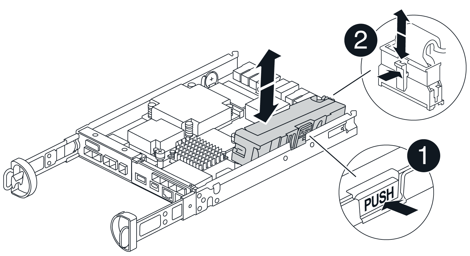

Battery release tab

Battery power connector
-
-
Move the battery to the replacement controller canister:
-
Align the battery with the holding brackets on the sheet metal side wall, but do not connect it. You will plug it in once the rest of the components are moved to the replacement controller canister.
-
-
If the replacement controller has pre-installed DIMMs, go to Step 7: Install the battery. Otherwise, continue to the next step.
Step 6: Move the DIMMs
Remove the DIMMs from the impaired controller canister and install them into the replacement controller canister.
-
Locate the DIMMs on your controller canister.
Note the location of the DIMM in the sockets so that you can insert the DIMM in the same location in the replacement controller canister and in the proper orientation. Remove the DIMMs from the impaired controller canister: -
Eject the DIMM from its slot by slowly pushing apart the two DIMM ejector tabs on either side of the DIMM.
The DIMM will rotate up a little.
-
Rotate the DIMM as far as it will go, and then slide the DIMM out of the socket.
Carefully hold the DIMM by the edges to avoid pressure on the components on the DIMM circuit board. 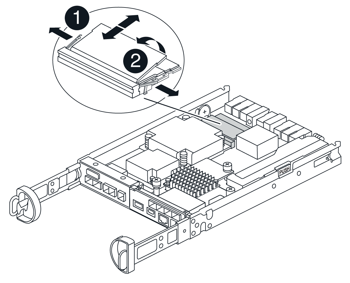
DIMM ejector tabs
DIMMS
-
-
Verify that the battery is not plugged into the replacement controller canister.
-
Install the DIMMs in the replacement controller in the same place they were in the impaired controller:
-
Push carefully, but firmly, on the top edge of the DIMM until the ejector tabs snap into place over the notches at the ends of the DIMM.
The DIMM fits tightly in the slot, but should go in easily. If not, realign the DIMM with the slot and reinsert it.
Visually inspect the DIMM to verify that it is evenly aligned and fully inserted into the slot.
-
-
Repeat these steps for the other DIMM.
-
If the replacement controller has a pre-installed battery, go to Step 8: Replace controller. Otherwise, continue to the next step.
Step 7: Install the battery
Install the battery into the replacement controller canister.
-
Plug the battery plug back into the socket on the controller canister.
Make sure that the plug locks down into the battery socket on the motherboard.
-
Align the battery with the holding brackets on the sheet metal side wall.
-
Slide the battery pack down until the battery latch engages and clicks into the opening on the side wall.
-
Reinstall the controller canister cover and lock it into place.
Step 8: Replace controller
Install the replacement controller and verify that the node has rejoined the grid.
-
Install the replacement controller into the appliance.
-
Turn the controller over, so that the removable cover faces down.
-
With the cam handle in the open position, slide the controller all the way into the appliance.
-
Move the cam handle to the left to lock the controller in place.
-
Replace the cables.
-
Power on the controller shelf.
-
Wait for the E4000 controller to reboot.
-
Determine how you will assign an IP address to the replacement controller.
The steps for assigning an IP address to the replacement controller depend on whether you connected the management port to a network with a DHCP server and on whether all drives are secured. If management port 1 is connected to a network with a DHCP server, the new controller will obtain its IP address from the DHCP server. This value might be different than the original controller's IP address.
-
-
If the storage array has secure drives, import the drive security key; otherwise, go to the next step. Follow the appropriate procedure below for a storage array with all secure drives or a mix of secure and unsecure drives.
Unsecure drives are unassigned drives, global hot spare drives, or drives that are part of a volume group or a pool that is not secured by the Drive Security feature. Secure drives are assigned drives that are a part of a secured volume group or disk pool using Drive Security. -
Only secured drives (no unsecure drives):
-
Access the storage array's command line interface (CLI). For more information on the CLI, see the E-series documentation.
-
Load the appropriate simplex NVSRAM on the controller.
For example:
download storageArray NVSRAM file=\"N4000-881834-SG4.dlp\" forceDownload=TRUE; -
Confirm that the controller is Optimal after loading simplex NVSRAM.
-
If using external security key management, setup external key management on the controller.
-
If using internal security key management, enter the following command to import the security key:
import storageArray securityKey file="C:/file.slk"
passPhrase="passPhrase";
where:
-
C:/file.slkrepresents the directory location and name of your drive security key -
passPhraseis the pass phrase needed to unlock the file After the security key has been imported, the controller reboots, and the new controller adopts the saved settings for the storage array.
-
-
Go to the next step to confirm that the new controller is Optimal.
-
-
Mix of secure and unsecure drives:
-
Collect the support bundle and open the storage array profile.
-
Find and record all the unsecure drives’ locations, which are found in the support bundle.
-
Power off the system.
-
Remove the unsecure drives.
-
Replace the controller.
-
Power on the system and wait for the seven-segment display to show the tray number.
-
From SANtricity System Manager, select Settings › System.
-
In the Security Key Management section, select Create/Change Key to create a new security key.
-
Select Unlock Secure Drives to import the security key you saved.
-
Run the
set allDrives nativeStateCLI command. -
The controller will reboot automatically.
-
Wait for the controller to boot up and for the seven-segment display to show the tray number or a flashing L5.
-
Power off the system.
-
Reinstall the unsecure drives.
-
Reset the controller using SANtricity System Manager.
-
Power on the system and wait for the seven-segment display to show the tray number.
-
Go to the next step to confirm that the new controller is Optimal.
-
-
-
If you placed the appliance into maintenance mode during this procedure, return the appliance to normal operating mode. From the StorageGRID Appliance Installer, select Advanced > Reboot Controller, and then select Reboot into StorageGRID.
-
During the reboot, monitor the node's status to determine when it has rejoined the grid.
The appliance reboots and rejoins the grid. This process can take up to 20 minutes.
-
Confirm that the reboot is complete and that the node has rejoined the grid:
-
In the Grid Manager, select Nodes.
-
Verify that the appliance node has a normal status (green check mark icon
 to the left of the node name), which indicates that no alerts are active and the node is connected to the grid.
-
-
From SANtricity System Manager, confirm that the new controller is Optimal.
-
Select Hardware.
-
For the controller shelf, select Show back of shelf.
-
Select the controller canister you replaced.
-
Select View settings.
-
Confirm that the controller's Status is Optimal.
-
If the status is not Optimal, highlight the controller, and select Place Online.
-
-
Collect support data for your storage array using SANtricity System Manager.
-
Select Support › Support Center › Diagnostics.
-
Select Collect Support Data.
-
Click Collect.
The file is saved in the Downloads folder for your browser with the name, support-data.7z.
-
After replacing the part, return the failed part to NetApp, as described in the RMA instructions shipped with the kit. See the Parts Return & Replacements page for further information.