5. Deploy and Configure the F5 Big-IP Virtual Edition Appliance
 Suggest changes


Anthos enables native integration with F5 Big-IP load balancers to expose services from each pod to the world.
This solution makes use of the virtual appliance deployed in VMware vSphere as deployed by NDE. Networking for the F5 Big-IP virtual appliance can be configured in a two-armed or three-armed configuration based on your network environment. The deployment in this document is based on the two-armed configuration. Additional details for configuring the virtual appliance for use with Anthos can be found here.
To deploy the F5 Big-IP Virtual Edition appliance, complete the following steps:
-
Download the virtual application Open Virtual Appliance (OVA) file from F5 here.
To download the appliance, a user must register with F5. They provide a 30-day demo license for the Big-IP Virtual Edition Load Balancer. NetApp recommends a permanent 10Gbps license for the production deployment of an appliance. -
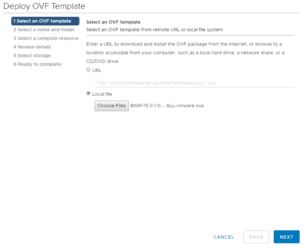
Right-click the infrastructure resource pool and select Deploy OVF Template. A wizard launches that allows you to select the OVA file that you just downloaded in Step 1. Click Next.
-
Click Next to continue through each step and accept the default values for each screen presented until you reach the storage selection screen. Select the VM_Datastore that was created earlier, and then click Next.
-
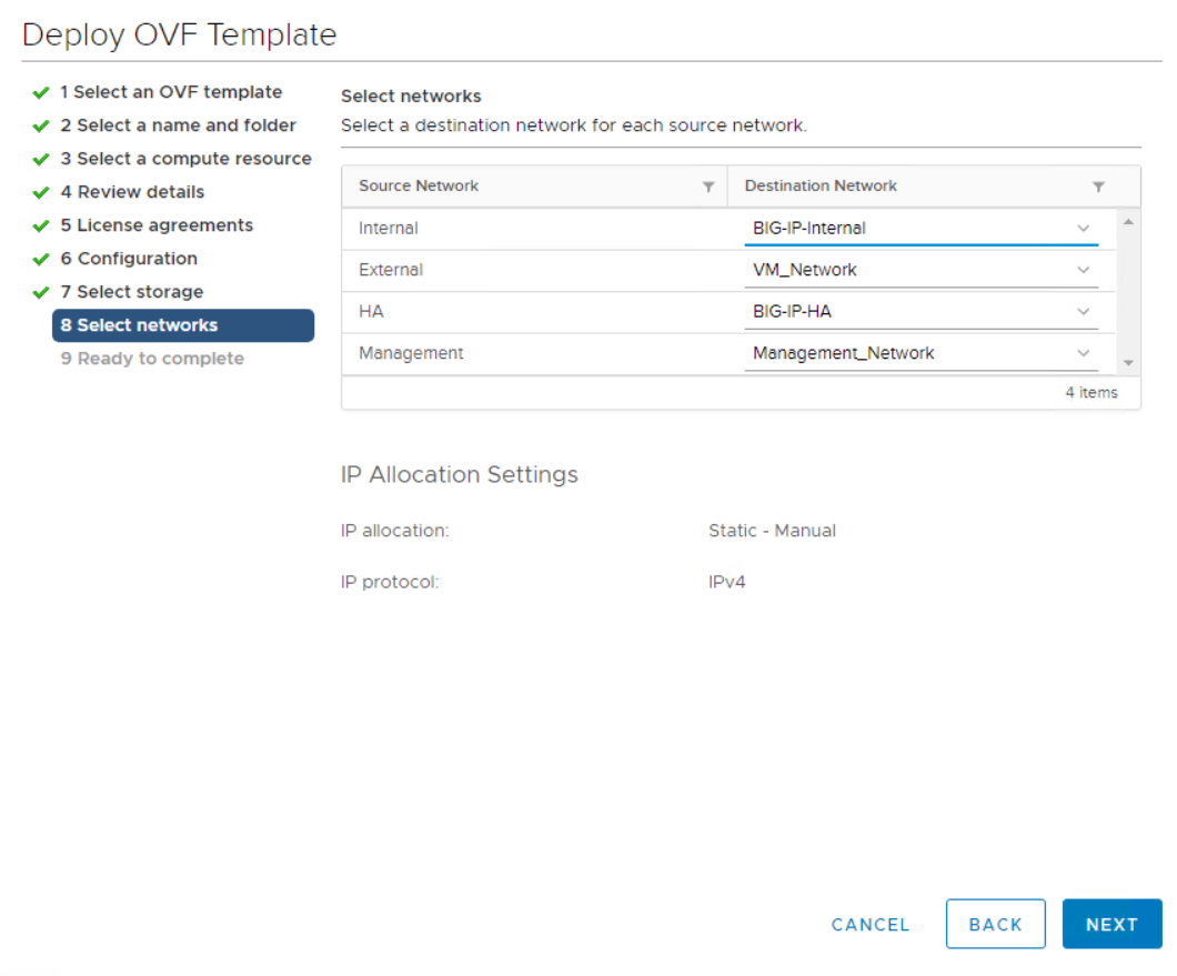
The next screen presented by the wizard allows you to customize the virtual networks for use in the environment. Select VM_Network for the External field and select Management_Network for the Management field. Internal and HA are used for advanced configurations for the F5 Big-IP appliance and are not configured. These parameters can be left alone, or they can be configured to connect to non-infrastructure, distributed port groups. Click Next.
-
Review the summary screen for the appliance, and, if all the information is correct, click Finish to start the deployment.
-
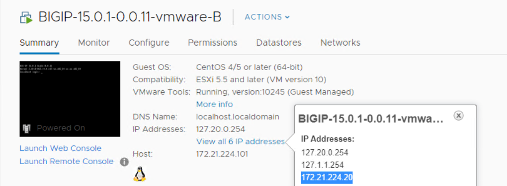
After the virtual appliance is deployed, right-click it and power it up. It should receive a DHCP address on the management network. The appliance is Linux-based, and it has VMware Tools deployed, so that you can view the DHCP address it receives in the vSphere client.
-
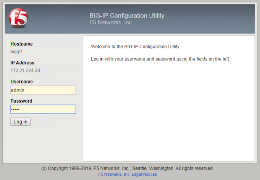
Open a web browser and connect to the appliance at the IP address from the previous step. The default login is admin/admin, and, after the first login, the appliance immediately prompts you to change the admin password. It then returns you to a screen where you must log in with the new credentials.
-
The first screen prompts the you to complete the Setup Utility. Begin the utility by clicking Next.
-
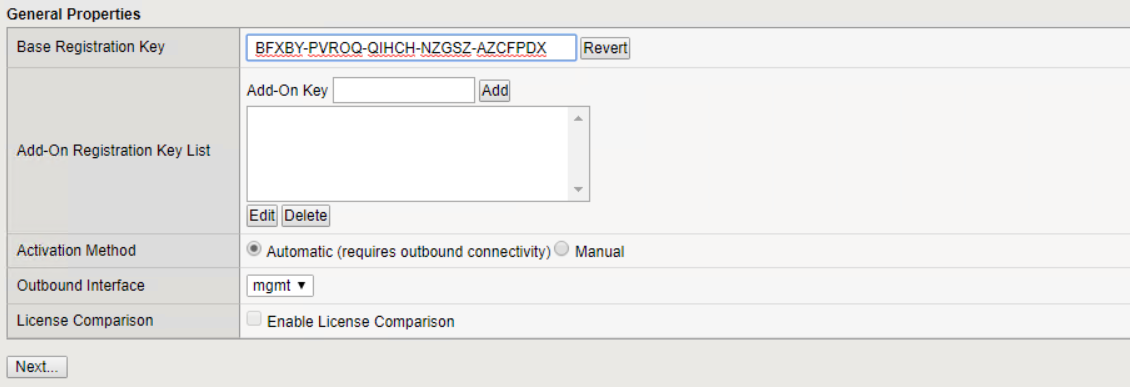
The next screen prompts you for activation of the appliance license. Click Activate to begin. When prompted on the next page, paste either the 30-day evaluation license key you received when you registered for the download or the permanent license you acquired when you purchased the appliance. Click Next.
For the device to perform activation, the network defined on the management interface must be able to reach the internet. -
On the next screen, the End User License Agreement (EULA) is presented. If the terms in the license are acceptable, click Accept.
-
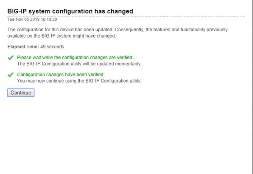
The next screen counts the elapsed time as it verifies the configuration changes that have been made so far. Click Continue to resume with the initial configuration.
-
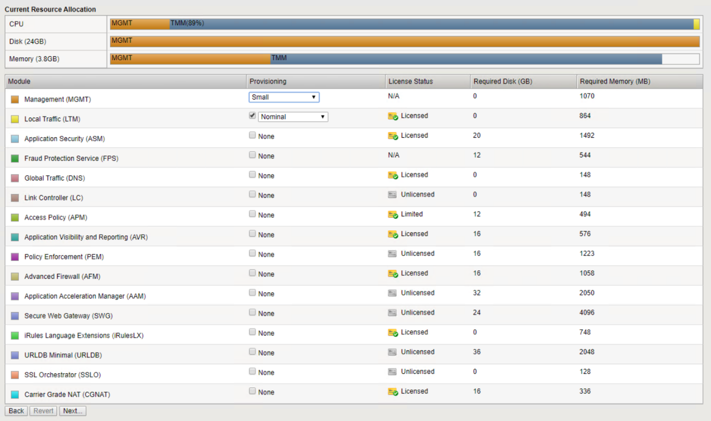
The Configuration Change window closes, and the Setup Utility displays the Resource Provisioning menu. This window lists the features that are currently licensed and the current resource allocations for the virtual appliance and each running service.
-
Clicking the Platform menu option on the left enables additional modification of the platform. Modifications include setting the management IP address configured with DHCP, setting the host name and the time zone the appliance is installed in, and securing the appliance from SSH accessibility.
-
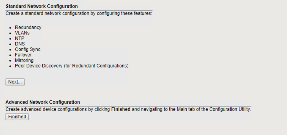
Next click the Network menu, which enables you to configure standard networking features. Click Next to begin the Standard Network Configuration wizard.
-
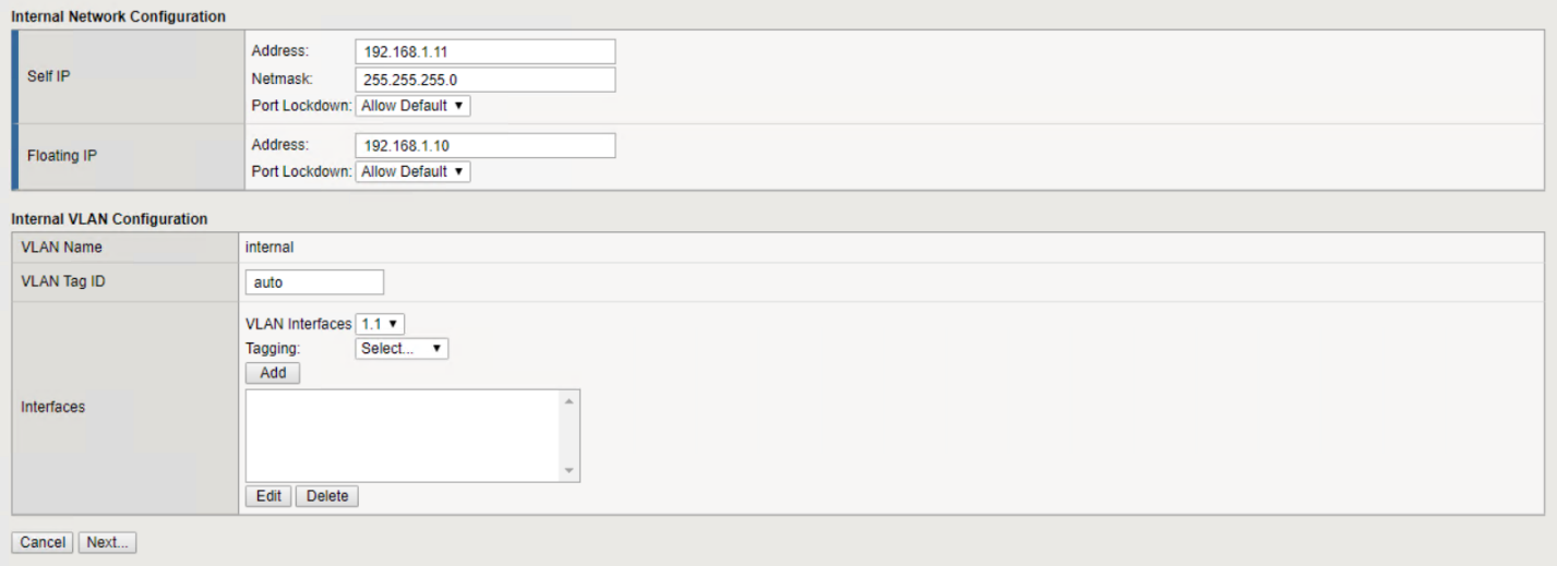
The first page of the wizard configures redundancy; leave the defaults and click Next. The next page enables you to configure an internal interface on the load balancer. Interface 1.1 maps to the vmnic labeled Internal in the OVF deployment wizard.
The fields in this page for Self IP Address, Netmask, and Floating IP address can be filled with a non-routable IP address for use as a placeholder. They can also be filled with an internal network that has been configured as a distributed port group for virtual guests if you are deploying the three-armed configuration. They must be completed to continue with the wizard. -
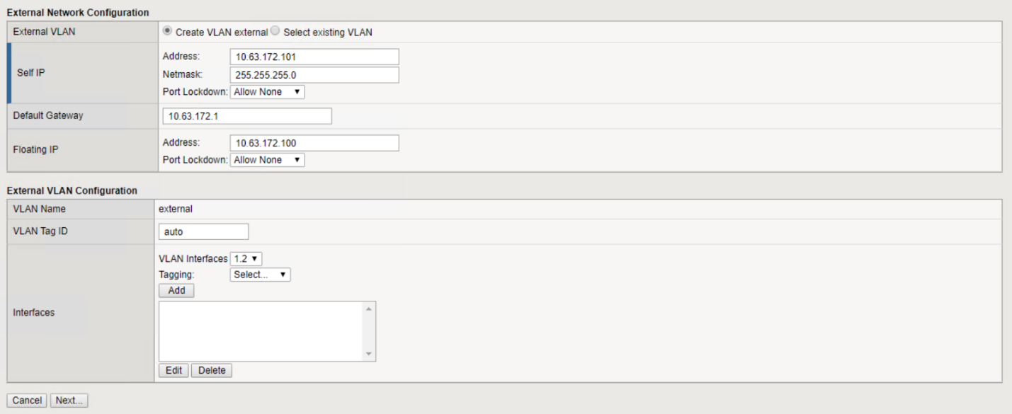
The next page enables you to configure an external network that is used to map services to the pods deployed in Kubernetes. Select a static IP from the VM_Network range, the appropriate subnet mask, and a floating IP from that same range. Interface 1.2 maps to the vmnic labeled External in the OVF deployment wizard.
-
On the next page, you can configure an internal-HA network if you are deploying multiple virtual appliances in the environment. To proceed, you must fill the Self-IP Address and the Netmask fields, and you must select interface 1.3 as the VLAN Interface, which maps to the HA network defined by the OVF template wizard.

-
The next page enables you to configure the NTP servers. Then click Next to continue to the DNS setup. The DNS servers and domain search list should already be populated by the DHCP server. Click Next to accept the defaults and continue.
-
For the remainder of the wizard, click Next to continue through the advanced peering setup, the configuration of which is beyond the scope of this document. Then click Finish to exit the wizard.
-
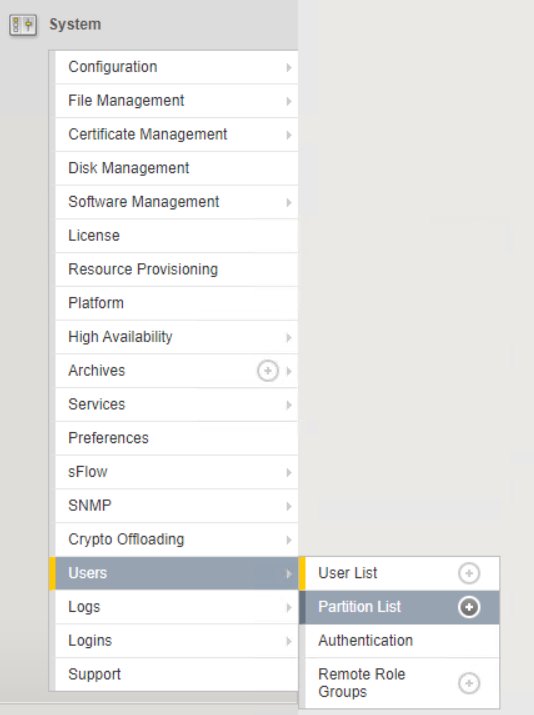
Create individual partitions for the Anthos admin cluster and each user cluster deployed in the environment. Click System in the menu on the left, navigate to Users, and click Partition List.
-
The displayed screen only shows the current common partition. Click Create on the right to create the first additional partition and name it
Anthos-Admin. Then click Repeat, name the partitionAnthos-Cluster1, and click the Repeat button again to name the next partitionAnthos-Cluster2. Finally click Finished to complete the wizard. The Partition list screen returns with all the partitions now listed.


