

Replace the DIMMs - E4000
 Suggest changes
You can replace a DIMM in the E4000 if a memory mismatch is present or you have a failed DIMM.
-
Make sure that no volumes are in use or that you have a multipath driver installed on all hosts using these volumes.
-
Make sure you have the following:
-
A replacement DIMM.
-
An ESD wristband, or you have taken other antistatic precautions.
-
A flat, static free work area.
-
Labels to identify each cable that is connected to the controller canister.
-
A management station with a browser that can access SANtricity System Manager for the controller. (To open the System Manager interface, point the browser to the controller’s domain name or IP address.)
-
Step 1: Determine if you need to replace a DIMM
Verify the cache size of your controller before replacing the DIMMS.
-
Access the Storage Array profile for the controller. From SANtricity System Manager, go to Support › Support Center. From the Support Resources page, select Storage Array Profile.
-
Scroll down or use the Search field to locate the Data Cache Module information.
-
If one of the following is present, note the DIMM’s location and continue with remaining procedures in this section to replace the DIMMs on your controller:
-
A failed DIMM, or a DIMM reporting Data Cache Module as not optimal.
-
A DIMM with a mismatched Data Cache Module capacity.
-
Step 2: Prepare to replace a DIMM
Prepare to replace a DIMM by saving the drive security key, backing up the configuration, and collecting support data. Then, you can stop host I/O operations and place the controller offline or power it down.
In a simplex configuration, power down the controller shelf so you can safely remove and replace the DIMMs.
-
Back up the storage array’s configuration database using SANtricity System Manager.
If a problem occurs when you remove a controller, you can use the saved file to restore your configuration. The system will save the current state of the RAID configuration database, which includes all data for volume groups and disk pools on the controller.
-
From System Manager:
-
Select Support › Support Center › Diagnostics.
-
Select Collect Configuration Data.
-
Click Collect.
The file is saved in the Downloads folder for your browser with the name, configurationData-<arrayName>-<dateTime>.7z.
-
-
Alternatively, you can back up the configuration database by using the following CLI command:
save storageArray dbmDatabase sourceLocation=onboard contentType=all file="filename";
-
-
Collect support data for your storage array using SANtricity System Manager.
If a problem occurs when you remove a controller, you can use the saved file to troubleshoot the issue. The system will save inventory, status, and performance data about your storage array in a single file.
-
Select Support › Support Center › Diagnostics.
-
Select Collect Support Data.
-
Click Collect.
The file is saved in the Downloads folder for your browser with the name, support-data.7z.
-
-
Ensure that no I/O operations are occurring between the storage array and all connected hosts. For example, you can perform these steps:
-
Stop all processes that involve the LUNs mapped from the storage to the hosts.
-
Ensure that no applications are writing data to any LUNs mapped from the storage to the hosts.
-
Unmount all file systems associated with volumes on the array.

The exact steps to stop host I/O operations depend on the host operating system and the configuration, which are beyond the scope of these instructions. If you are not sure how to stop host I/O operations in your environment, consider shutting down the host. 
Possible data loss--If you continue this procedure while I/O operations are occurring, you might lose data.
-
-
Wait for any data in cache memory to be written to the drives.
The green Cache Active LED on the back of the controller is on when cached data needs to be written to the drives. You must wait for this LED to turn off.
-
From the home page of SANtricity System Manager, select View Operations in Progress.
-
Confirm that all operations have completed before continuing with the next step.
-
Turn off both power switches on the controller shelf.
-
Wait for all LEDs on the controller shelf to turn off.
In a duplex configuration, place the controller offline so you can safely remove and replace the DIMMs.
-
From SANtricity System Manager, review the details in the Recovery Guru to confirm that there is an issue with a mismatched memory and to ensure no other items must be addressed first.
-
From the Details area of the Recovery Guru, determine which DIMM to replace.
-
Back up the storage array’s configuration database using SANtricity System Manager.
If a problem occurs when you remove a controller, you can use the saved file to restore your configuration. The system will save the current state of the RAID configuration database, which includes all data for volume groups and disk pools on the controller.
-
From System Manager:
-
Select Support › Support Center › Diagnostics.
-
Select Collect Configuration Data.
-
Click Collect.
The file is saved in the Downloads folder for your browser with the name, configurationData- <arrayName>-<dateTime>.7z.
-
-
-
If the controller is not already offline, take it offline now using SANtricity System Manager.
-
Select Hardware.
-
If the graphic shows the drives, select Show back of shelf to show the controllers.
-
Select the controller that you want to place offline.
-
From the context menu, select Place offline, and confirm that you want to perform the operation.
If you are accessing SANtricity System Manager using the controller you are attempting to take offline, a SANtricity System Manager Unavailable message is displayed. Select Connect to an alternate network connection to automatically access SANtricity System Manager using the other controller.
-
-
Wait for SANtricity System Manager to update the controller’s status to offline.
Do not begin any other operations until after the status has been updated. -
Select Recheck from the Recovery Guru, and confirm that the OK to remove field in the Details area displays Yes, indicating that it is safe to remove this component.
Step 3: Remove controller canister
Remove the controller canister from the system and then remove the controller canister cover.
-
If you are not already grounded, properly ground yourself.
-
Loosen the hook and loop strap binding the cables to the cable management device, and then unplug the system cables and SFPs (if needed) from the controller canister, keeping track of where the cables were connected.
Leave the cables in the cable management device so that when you reinstall the cable management device, the cables are organized.
-
Remove and set aside the cable management devices from the left and right sides of the controller canister.
-
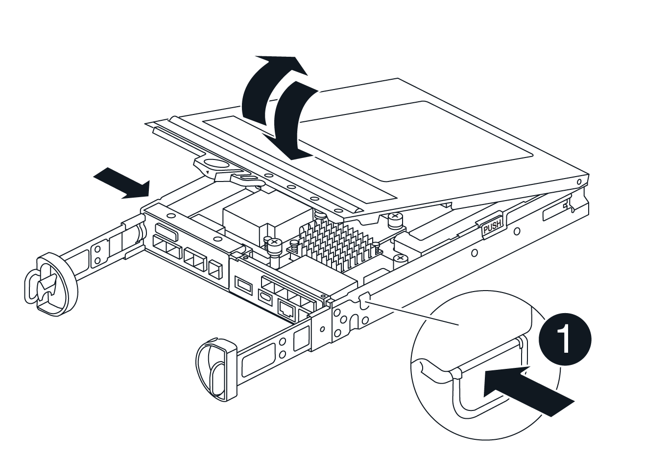
Squeeze the latch on the cam handle until it releases, open the cam handle fully to release the controller canister from the midplane, and then, using two hands, pull the controller canister out of the chassis.
-
Confirm that the Cache Active LED on the back of the controller is off.
-
Turn the controller canister over and place it on a flat, stable surface.
-
Open the cover by pressing the blue buttons on the sides of the controller canister to release the cover, and then rotate the cover up and off of the controller canister.
Step 4: Replace the DIMMs
Locate the DIMM inside the controller, remove it, and replace it.
-
If you are not already grounded, properly ground yourself.
-
Locate the DIMMs on your controller canister.
-
Note the orientation and location of the DIMM in the socket so that you can insert the replacement DIMM in the proper orientation.
-
Eject the DIMM from its slot by slowly pushing apart the two DIMM ejector tabs on either side of the DIMM, and then slide the DIMM out of the slot.
The DIMM will rotate up a little.
-
Rotate the DIMM as far as it will go, and then slide the DIMM out of the socket.
Carefully hold the DIMM by the edges to avoid pressure on the components on the DIMM circuit board. 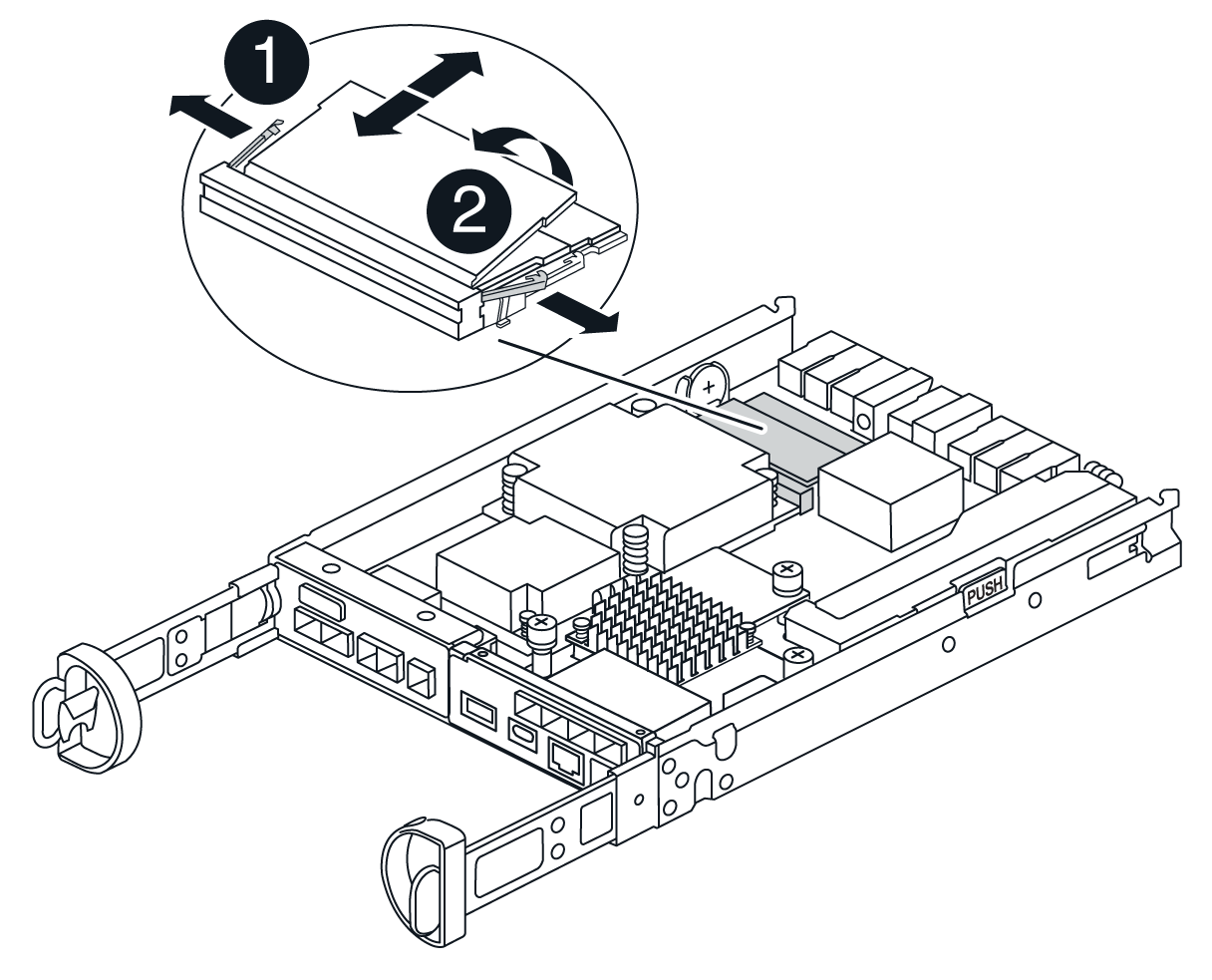

DIMM ejector tabs

DIMMS
-
Remove the replacement DIMM from the antistatic shipping bag, hold the DIMM by the corners, and align it to the slot.
The notch among the pins on the DIMM should line up with the tab in the socket.
-
Insert the DIMM squarely into the slot.
The DIMM fits tightly in the slot, but should go in easily. If not, realign the DIMM with the slot and reinsert it.
Visually inspect the DIMM to verify that it is evenly aligned and fully inserted into the slot. -
Push carefully, but firmly, on the top edge of the DIMM until the ejector tabs snap into place over the notches at the ends of the DIMM.
-
Reinstall the controller canister cover.
Step 5: Reinstall the controller canister
Reinstall the controller canister into the chassis.
-
If you are not already grounded, properly ground yourself.
-
If you have not already done so, replace the cover on the controller canister.
-
Turn the controller over, so that the removable cover faces down.
-
With the cam handle in the open position, slide the controller all the way into the shelf.
-
Replace the cables.
If you removed the media converters (QSFPs or SFPs), remember to reinstall them if you are using fiber optic cables. -
Bind the cables to the cable management device with the hook and loop strap.
Step 6: Complete DIMMs replacement
Place the controller online, collect support data, and resume operations.
-
As the controller boots, check the controller LEDs.
When communication with the other controller is reestablished:
-
The amber Attention LED remains on.
-
The Host Link LEDs might be on, blinking, or off, depending on the host interface.
-
-
When the controller is back online, confirm that its status is Optimal and check the controller shelf’s Attention LEDs.
If the status is not Optimal or if any of the Attention LEDs are on, confirm that all cables are correctly seated and the controller canister is installed correctly. If necessary, remove and reinstall the controller canister. NOTE: If you cannot resolve the problem, contact technical support.
-
Collect support data for your storage array using SANtricity System Manager.
-
Select Support › Support Center › Diagnostics.
-
Select Collect Support Data.
-
Click Collect.
The file is saved in the Downloads folder for your browser with the name, support-data.7z.
-
Place the controller online, collect support data, and resume operations.
-
Place controller online.
-
In System Manager, navigate to the Hardware page.
-
Select Controllers & Components.
-
Select the controller with the replaced DIMMs.
-
Select Place online from the drop-down list.
-
-
As the controller boots, check the controller LEDs.
When communication with the other controller is reestablished:
-
The amber Attention LED remains on.
-
The Host Link LEDs might be on, blinking, or off, depending on the host interface.
-
-
When the controller is back online, confirm that its status is Optimal and check the controller shelf’s Attention LEDs.
If the status is not Optimal or if any of the Attention LEDs are on, confirm that all cables are correctly seated and the controller canister is installed correctly. If necessary, remove and reinstall the controller canister. NOTE: If you cannot resolve the problem, contact technical support.
-
Verify that all volumes have been returned to the preferred owner.
-
Select Storage › Volumes. From the All Volumes page, verify that volumes are distributed to their preferred owners. Select More › Change ownership to view volume owners.
-
If volumes are all owned by preferred owner continue to Step 6.
-
If none of the volumes are returned, you must manually return the volumes. Go to More › Redistribute volumes.
-
If there is no Recovery Guru present or if following the Recovery Guru steps the volumes are still not returned to their preferred owners contact support.
-
-
Collect support data for your storage array using SANtricity System Manager.
-
Select Support › Support Center › Diagnostics.
-
Select Collect Support Data.
-
Click Collect.
The file is saved in the Downloads folder for your browser with the name, support-data.7z.
-