

Upgrade controllers from AFF A700/FAS9000 to AFF A900/FAS9500 in a MetroCluster IP configuration using switchover and switchback (ONTAP 9.10.1 or later)
 Suggest changes
You can use the MetroCluster switchover operation to provide nondisruptive service to clients while the controller modules on the partner cluster are upgraded. Other components (such as storage shelves or switches) cannot be upgraded as part of this procedure.
-
To upgrade AFF A700 controller modules to AFF A900, the controllers must be running ONTAP 9.10.1 or later.
-
To upgrade FAS9000 controller modules to FAS9500, the controllers must be running ONTAP 9.10.1P3 or later.
-
All controllers in the configuration should be upgraded during the same maintenance period.
Operating the MetroCluster configuration with an AFF A700 and an AFF A900, or a FAS9000 and a FAS9500 controller is not supported outside of this maintenance activity.
-
The IP switches must be running a supported firmware version.
-
You will reuse the IP addresses, netmasks, and gateways of the original platforms on the new platforms.
-
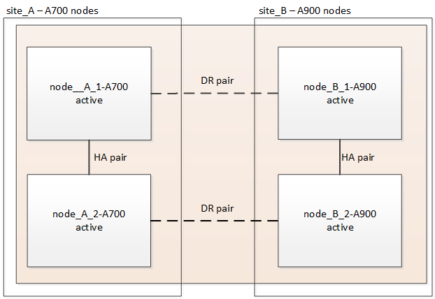
The following example names are used in this procedure, in both examples and graphics:
-
Site_A
-
Before upgrade:
-
node_A_1-A700
-
node_A_2-A700
-
-
After upgrade:
-
node_A_1-A900
-
node_A_2-A900
-
-
-
Site_B
-
Before upgrade:
-
node_B_1-A700
-
node_B_2-A700
-
-
After upgrade:
-
node_B_1-A900
-
node_B_2-A900
-
-
-
Enable console logging
NetApp strongly recommends that you enable console logging on the devices that you are using and take the following actions when performing this procedure:
-
Leave AutoSupport enabled during maintenance.
-
Trigger a maintenance AutoSupport message before and after maintenance to disable case creation for the duration of the maintenance activity.
See the Knowledge Base article How to suppress automatic case creation during scheduled maintenance windows.
-
Enable session logging for any CLI session. For instructions on how to enable session logging, review the "Logging Session Output" section in the Knowledge Base article How to configure PuTTY for optimal connectivity to ONTAP systems.
Workflow for upgrading controllers in a MetroCluster IP configuration
You can use the workflow diagram to help you plan the upgrade tasks.
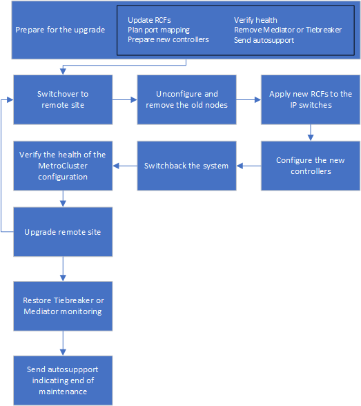
Prepare for the upgrade
Before making any changes to the existing MetroCluster configuration, you must check the health of the configuration, prepare the new platforms, and perform other miscellaneous tasks.
Clear slot 7 on the AFF A700 or FAS9000 controller
The MetroCluster configuration on an AFF A900 or FAS9500 uses one of each of the ports on the DR cards located in slots 5 and 7. Before starting the upgrade, if there are cards in slot 7 on the AFF A700 or FAS9000, you must move them to other slots for all the nodes of the cluster.
Update the MetroCluster switch RCF files before upgrading controllers
You must update the RCF files on MetroCluster switches when performing this upgrade. The following table provides the VLAN ranges supported for AFF A900/FAS9500 MetroCluster IP configurations.
Platform model |
Supported VLAN IDs |
|---|---|
|
|
-
If the switch is not configured with the minimum supported RCF file version, you must update the RCF file. For the correct RCF file version for your switch model, refer to the RcfFileGenerator Tool. The following steps are for the RCF file application.
-
Prepare the IP switches for the application of the new RCF files.
Follow the steps in the section for your switch vendor:
-
Download and install the RCF files.
Follow the steps in the section for your switch vendor:
Map ports from the old nodes to the new nodes
When upgrading from an AFF A700 to an AFF A900, or FAS9000 to FAS9500, you do not change the data network ports, FCP SAN adapter ports, and SAS and NVMe storage ports. Data LIFs stay where they are during and after the upgrade. Therefore, you are not required to map the network ports from the old nodes to the new nodes.
Verify MetroCluster health before site upgrade
You verify the health and connectivity of the MetroCluster configuration before performing the upgrade.

|
After you upgrade the controllers at the first site and before you upgrade the second, running metrocluster check run followed by metrocluster check show returns an error in the config-replication field. This error indicates an NVRAM size mismatch between the nodes at each site and it's the expected behavior when there are different platform models on both sites. You can ignore the error until the controller upgrade is completed for all nodes in the DR group.
|
-
Verify the operation of the MetroCluster configuration in ONTAP:
-
Check whether the nodes are multipathed:
node run -node node-name sysconfig -aYou should issue this command for each node in the MetroCluster configuration.
-
Verify that there are no broken disks in the configuration:
storage disk show -brokenYou should issue this command on each node in the MetroCluster configuration.
-
Check for any health alerts:
system health alert showYou should issue this command on each cluster.
-
Verify the licenses on the clusters:
system license showYou should issue this command on each cluster.
-
Verify the devices connected to the nodes:
network device-discovery showYou should issue this command on each cluster.
-
Verify that the time zone and time is set correctly on both sites:
cluster date showYou should issue this command on each cluster. You can use the
cluster datecommand to configure the time and time zone.
-
-
Confirm the operational mode of the MetroCluster configuration and perform a MetroCluster check.
-
Confirm the MetroCluster configuration and that the operational mode is
normal:
metrocluster show -
Confirm that all expected nodes are shown:
metrocluster node show -
Issue the following command:
metrocluster check run -
Display the results of the MetroCluster check:
metrocluster check show
-
-
Check the MetroCluster cabling with the Config Advisor tool.
-
Download and run Config Advisor.
-
After running Config Advisor, review the tool's output and follow the recommendations in the output to address any issues discovered.
-
Gather information before the upgrade
Before upgrading, you must gather information for each of the nodes, and, if necessary, adjust the network broadcast domains, remove any VLANs and interface groups, and gather encryption information.
-
Record the physical cabling for each node, labelling cables as needed to allow correct cabling of the new nodes.
-
Gather the output of the following commands for each node:
-
metrocluster interconnect show -
metrocluster configuration-settings connection show -
network interface show -role cluster,node-mgmt -
network port show -node node_name -type physical -
network port vlan show -node node-name -
network port ifgrp show -node node_name -instance -
network port broadcast-domain show -
network port reachability show -detail -
network ipspace show -
volume show -
storage aggregate show -
system node run -node node-name sysconfig -a -
vserver fcp initiator show -
storage disk show -
metrocluster configuration-settings interface show
-
-
Gather the UUIDs for the site_B (the site whose platforms are currently being upgraded):
metrocluster node show -fields node-cluster-uuid, node-uuidThese values must be configured accurately on the new site_B controller modules to ensure a successful upgrade. Copy the values to a file so that you can copy them into the proper commands later in the upgrade process.
The following example shows the command output with the UUIDs:cluster_B::> metrocluster node show -fields node-cluster-uuid, node-uuid (metrocluster node show) dr-group-id cluster node node-uuid node-cluster-uuid ----------- --------- -------- ------------------------------------ ------------------------------ 1 cluster_A node_A_1-A700 f03cb63c-9a7e-11e7-b68b-00a098908039 ee7db9d5-9a82-11e7-b68b-00a098908039 1 cluster_A node_A_2-A700 aa9a7a7a-9a81-11e7-a4e9-00a098908c35 ee7db9d5-9a82-11e7-b68b-00a098908039 1 cluster_B node_B_1-A700 f37b240b-9ac1-11e7-9b42-00a098c9e55d 07958819-9ac6-11e7-9b42-00a098c9e55d 1 cluster_B node_B_2-A700 bf8e3f8f-9ac4-11e7-bd4e-00a098ca379f 07958819-9ac6-11e7-9b42-00a098c9e55d 4 entries were displayed. cluster_B::*
It is recommended that you record the UUIDs into a table similar to the following.
Cluster or node
UUID
cluster_B
07958819-9ac6-11e7-9b42-00a098c9e55d
node_B_1-A700
f37b240b-9ac1-11e7-9b42-00a098c9e55d
node_B_2-A700
bf8e3f8f-9ac4-11e7-bd4e-00a098ca379f
cluster_A
ee7db9d5-9a82-11e7-b68b-00a098908039
node_A_1-A700
f03cb63c-9a7e-11e7-b68b-00a098908039
node_A_2-A700
aa9a7a7a-9a81-11e7-a4e9-00a098908c35
-
If the MetroCluster nodes are in a SAN configuration, collect the relevant information.
You should gather the output of the following commands:
-
fcp adapter show -instance -
fcp interface show -instance -
iscsi interface show -
ucadmin show
-
-
If the root volume is encrypted, collect and save the passphrase used for key-manager:
security key-manager backup show -
If the MetroCluster nodes are using encryption for volumes or aggregates, copy information about the keys and passphrases. For additional information, see Backing up onboard key management information manually.
-
If Onboard Key Manager is configured:
security key-manager onboard show-backup
You will need the passphrase later in the upgrade procedure. -
If enterprise key management (KMIP) is configured, issue the following commands:
security key-manager external show -instance
security key-manager key query
-
-
Gather the system IDs of the existing nodes:
metrocluster node show -fields node-systemid,ha-partner-systemid,dr-partner-systemid,dr-auxiliary-systemidThe following output shows the reassigned drives.
::> metrocluster node show -fields node-systemid,ha-partner-systemid,dr-partner-systemid,dr-auxiliary-systemid

dr-group-id cluster     node     node-systemid ha-partner-systemid dr-partner-systemid dr-auxiliary-systemid
----------- ----------- -------- ------------- ------------------- ------------------- ---------------------
1           cluster_A node_A_1-A700   537403324     537403323           537403321           537403322
1           cluster_A node_A_2-A700   537403323     537403324           537403322          537403321
1           cluster_B node_B_1-A700   537403322     537403321           537403323          537403324
1           cluster_B node_B_2-A700   537403321     537403322           537403324          537403323
4 entries were displayed.
Remove Mediator or Tiebreaker monitoring
Before the upgrading the platforms, you must remove monitoring if the MetroCluster configuration is monitored with the Tiebreaker or Mediator utility.
-
Collect the output for the following command:
storage iscsi-initiator show -
Remove the existing MetroCluster configuration from Tiebreaker, Mediator, or other software that can initiate switchover.
If you are using…
Use this procedure…
Tiebreaker
Removing MetroCluster Configurations in the MetroCluster Tiebreaker Installation and Configuration content
Mediator
Issue the following command from the ONTAP prompt:
metrocluster configuration-settings mediator removeThird-party applications
Refer to the product documentation.
Send a custom AutoSupport message prior to maintenance
Before performing the maintenance, you should issue an AutoSupport message to notify technical support that maintenance is underway. Informing technical support that maintenance is underway prevents them from opening a case on the assumption that a disruption has occurred.
This task must be performed on each MetroCluster site.
-
Log in to the cluster.
-
Invoke an AutoSupport message indicating the start of the maintenance:
system node autosupport invoke -node * -type all -message MAINT=maintenance-window-in-hoursThe
maintenance-window-in-hoursparameter specifies the length of the maintenance window, with a maximum of 72 hours. If the maintenance is completed before the time has elapsed, you can invoke an AutoSupport message indicating the end of the maintenance period:system node autosupport invoke -node * -type all -message MAINT=end -
Repeat these steps on the partner site.
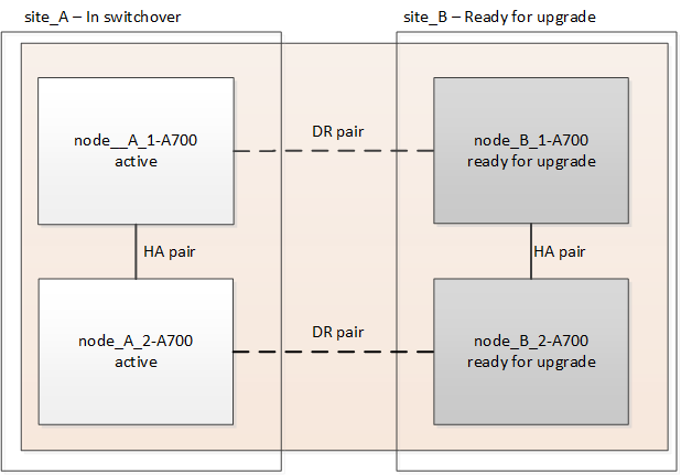
Switch over the MetroCluster configuration
You must switch over the configuration to site_A so that the platforms on site_B can be upgraded.
This task must be performed on site_A.
After completing this task, site_A is active and serving data for both sites. site_B is inactive, and ready to begin the upgrade process.
-
Switch over the MetroCluster configuration to site_A so that site_B's nodes can be upgraded:
-
Issue the following command on site_A:
metrocluster switchover -controller-replacement trueThe operation can take several minutes to complete.
-
Monitor the switchover operation:
metrocluster operation show -
After the operation is complete, confirm that the nodes are in switchover state:
metrocluster show -
Check the status of the MetroCluster nodes:
metrocluster node showAutomatic healing of aggregates after negotiated switchover is disabled during controller upgrade. Nodes at site_B are halted and stopped at the
LOADERprompt.
-
Remove AFF A700 or FAS9000 platform controller module and NVS
If you are not already grounded, properly ground yourself.
-
Gather the bootarg values from both nodes at site_B:
printenv -
Power off the chassis at site_B.
Remove the AFF A700 or FAS9000 controller module
Use the following procedure to remove the AFF A700 or FAS9000 controller module
-
Detach the console cable, if any, and the management cable from the controller module before removing the controller module.
-
Unlock and remove the controller module from the chassis.
-
Slide the orange button on the cam handle downward until it unlocks.
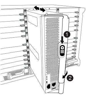

Cam handle release button

Cam handle
-
Rotate the cam handle so that it completely disengages the controller module from the chassis, and then slide the controller module out of the chassis. Make sure that you support the bottom of the controller module as you slide it out of the chassis.
-
Remove the AFF A700 or FAS9000 NVS module
Use the following procedure to remove the AFF A700 or FAS9000 NVS module.
Note: The NVS module is in slot 6 and is double the height compared to other modules in the system.
-
Unlock and remove the NVS from slot 6.
-
Depress the lettered and numbered 'cam' button. The cam button moves away from the chassis.
-
Rotate the cam latch down until it is in a horizontal position. The NVS disengages from the chassis and moves a few inches.
-
Remove the NVS from the chassis by pulling on the pull tabs on the sides of the module face.
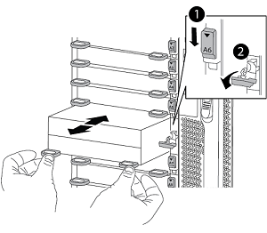
Lettered and numbered I/O cam latch
I/O latch completely unlocked
-
-
If you are using add-on modules used as coredump devices on the AFF A700 or FAS9000 NVS, do not transfer them to the AFF A900 or FAS9500 NVS. Do not transfer any parts from the AFF A700 or FAS9000 controller module and NVS to the AFF A900 or FAS9500 module.
Install the AFF A900 or FAS9500 NVS and controller modules
You must install the AFF A900 or FAS9500 NVS and controller module that you received in the upgrade kit on both nodes at site_B. Do not move the coredump device from the AFF A700 or FAS9000 NVS module to the AFF A900 or FAS9500 NVS module.
If you are not already grounded, properly ground yourself.
Install the AFF A900 or FAS9500 NVS
Use the following procedure to install the AFF A900 or FAS9500 NVS in slot 6 of both nodes at site_B.
-
Align the NVS with the edges of the chassis opening in slot 6.
-
Gently slide the NVS into the slot until the lettered and numbered I/O cam latch begins to engage with the I/O cam pin, and then push the I/O cam latch all the way up to lock the NVS in place.
Lettered and numbered I/O cam latch
I/O latch completely unlocked
Install the AFF A900 or FAS9500 controller module.
Use the following procedure to install the AFF A900 or FAS9500 controller module.
-
Align the end of the controller module with the opening in the chassis, and then gently push the controller module halfway into the system.
-
Firmly push the controller module into the chassis until it meets the midplane and is fully seated. The locking latch rises when the controller module is fully seated. Attention: To avoid damaging the connectors, do not use excessive force when sliding the controller module into the chassis.
-
Cable the management and console ports to the controller module.
Cam handle release button
Cam handle
-
Install the second X91146A card in slot 7 of each node.
-
Move the e5b connection to e7b.
-
Move the e5a connection to e5b.

Slot 7 on all nodes of the cluster should be empty as mentioned in the Map ports from the old nodes to the new nodes section.
-
-
Power ON the chassis and connect to serial console.
-
After BIOS initialization, if the node starts autoboot, interrupt the AUTOBOOT by pressing Control-C.
-
After autoboot is interrupted, the nodes stop at the LOADER prompt. If you do not interrupt autoboot on time and node1 starts booting, wait for the prompt to press Ctrl-C to go into the boot menu. After the node stops at the boot menu, use option 8 to reboot the node and interrupt the autoboot during reboot.
-
At the LOADER prompt, set the default environment variables: set-defaults
-
Save the default environment variables settings:
saveenv
Netboot nodes at site_B
After swapping the AFF A900 or FAS9500 controller module and NVS, you need to netboot the AFF A900 or FAS9500 nodes and install the same ONTAP version and patch level that is running on the cluster. The term netboot means you are booting from an ONTAP image stored on a remote server. When preparing for netboot, you must add a copy of the ONTAP 9 boot image onto a web server that the system can access.
It is not possible to check the version of ONTAP installed on the boot media of an AFF A900 or FAS9500 controller module unless it is installed in a chassis and powered ON. The ONTAP version on the AFF A900 or FAS9500 boot media must be the same as the ONTAP version running on the AFF A700 or FAS9000 system that is being upgraded and both the primary and backup boot images should match. You can configure the images by performing a netboot followed by the wipeconfig command from the boot menu. If the controller module was previously used in another cluster, the wipeconfig command clears any residual configuration on the boot media.
-
Verify that you can access a HTTP server with the system.
-
You need to download the necessary system files for your system and the correct version of ONTAP from the NetApp Support Site.
You must netboot the new controllers, if the version of ONTAP installed is not the same as the version installed on the original controllers. After you install each new controller, you boot the system from the ONTAP 9 image stored on the web server. You can then download the correct files to the boot media device for subsequent system boots.
-
Access the NetApp Support Site to download the files used for performing the netboot of the system.
-
Download the appropriate ONTAP software from the software download section of the NetApp Support Site and store the
ontap-version_image.tgzfile on a web-accessible directory. -
Change to the web-accessible directory and verify that the files you need are available.
-
Your directory listing should contain <ontap_version>\_image.tgz.
-
Configure the netboot connection by choosing one of the following actions.
You should use the management port and IP as the netboot connection. Do not use a data LIF IP or a data outage might occur while the upgrade is being performed. If the Dynamic Host Configuration Protocol (DCHP) is…
Then…
Running
Configure the connection automatically by using the following command at the boot environment prompt:
ifconfig e0M -autoNot Running
Manually configure the connection by using the following command at the boot environment prompt:
ifconfig e0M -addr=<filer_addr> -mask=<netmask> -gw=<gateway> - dns=<dns_addr> domain=<dns_domain><filer_addr>is the IP address of the storage system.<netmask>is the network mask of the storage system.<gateway>is the gateway for the storage system.<dns_addr>is the IP address of a name server on your network. This parameter is optional.<dns_domain>is the Domain Name Service (DNS) domain name. This parameter is optional. NOTE: Other parameters might be necessary for your interface. Enterhelp ifconfigat the firmware prompt for details. -
Perform netboot on node_B_1:
netboothttp://<web_server_ip/path_to_web_accessible_directory>/netboot/kernelThe
<path_to_the_web-accessible_directory>should lead to where you downloaded the<ontap_version>\_image.tgzin Step 2.
Do not interrupt the boot. -
Wait for the node_B_1 now running on the AFF A900 or FAS9500 controller module to boot and display the boot menu options as shown below:
Please choose one of the following:

(1)  Normal Boot.
(2)  Boot without /etc/rc.
(3)  Change password.
(4)  Clean configuration and initialize all disks.
(5)  Maintenance mode boot.
(6)  Update flash from backup config.
(7)  Install new software first.
(8)  Reboot node.
(9)  Configure Advanced Drive Partitioning.
(10) Set Onboard Key Manager recovery secrets.
(11) Configure node for external key management.
Selection (1-11)?
-
From the boot menu, select option
(7) Install new software first.This menu option downloads and installs the new ONTAP image to the boot device. NOTE: Disregard the following message:This procedure is not supported for Non-Disruptive Upgrade on an HA pair.This note applies to nondisruptive ONTAP software upgrades, and not controller upgrades.Always use netboot to update the new node to the desired image. If you use another method to install the image on the new controller, the incorrect image might install. This issue applies to all ONTAP releases.
-
If you are prompted to continue the procedure, enter
y, and when prompted for the package, enter the URL:http://<web_server_ip/path_to_web-accessible_directory>/<ontap_version>\_image.tgz -
Complete the following substeps to reboot the controller module:
-
Enter
nto skip the backup recovery when you see the following prompt:Do you want to restore the backup configuration now? {y|n} n -
Enter
yto reboot when you see the following prompt:The node must be rebooted to start using the newly installed software. Do you want to reboot now? {y|n} yThe controller module reboots but stops at the boot menu because the boot device was reformatted, and the configuration data needs to be restored.
You must reboot the node in order to use the newly installed software.
-
-
At the prompt, run the
wipeconfigcommand to clear any previous configuration on the boot media:-
When you see the following message, answer
yes:This will delete critical system configuration, including cluster membership. Warning: do not run this option on a HA node that has been taken over. Are you sure you want to continue?: -
The node reboots to finish the
wipeconfigand then stops at the boot menu.
-
-
Select option
5to go to maintenance mode from the boot menu. Answeryesto the prompts until the node stops at maintenance mode and the command prompt \*>. -
Repeat these steps to netboot node_B_2.
Restore the HBA configuration
Depending on the presence and configuration of HBA cards in the controller module, you need to configure them correctly for your site's usage.
-
In Maintenance mode configure the settings for any HBAs in the system:
-
Check the current settings of the ports:
ucadmin show -
Update the port settings as needed.
If you have this type of HBA and desired mode…
Use this command…
CNA FC
ucadmin modify -m fc -t initiator adapter-nameCNA Ethernet
ucadmin modify -mode cna adapter-nameFC target
fcadmin config -t target adapter-nameFC initiator
fcadmin config -t initiator adapter-name -
-
Exit Maintenance mode:
haltAfter you run the command, wait until the node stops at the LOADER prompt.
-
Boot the node back into Maintenance mode to enable the configuration changes to take effect:
boot_ontap maint -
Verify the changes you made:
If you have this type of HBA…
Use this command…
CNA
ucadmin showFC
fcadmin show
Set the HA state on the new controllers and chassis
You must verify the HA state of the controllers and chassis, and, if necessary, update the state to match your system configuration.
-
In Maintenance mode, display the HA state of the controller module and chassis:
ha-config showThe HA state for all components should be
mccip. -
If the displayed system state of the controller or chassis is not correct, set the HA state:
ha-config modify controller mccipha-config modify chassis mccip -
Halt the node:
haltThe node should stop at the
LOADER>prompt. -
On each node, check the system date, time, and time zone:
show date -
If necessary, set the date in UTC or GMT:
set date <mm/dd/yyyy> -
Check the time by using the following command at the boot environment prompt:
show time -
If necessary, set the time in UTC or GMT:
set time <hh:mm:ss> -
Save the settings:
saveenv -
Gather environment variables:
printenv
Update the switch RCF files to accommodate the new platforms
You must update the switches to a configuration that supports the new platform models.
You perform this task at the site containing the controllers that are currently being upgraded. In the examples shown in this procedure we are upgrading site_B first.
The switches at site_A will be upgraded when the controllers on site_A are upgraded.
-
Prepare the IP switches for the application of the new RCFs.
Follow the steps in the section for your switch vendor:
-
Download and install the RCFs.
Follow the steps in the section for your switch vendor:
Configure the new controllers
New controllers should be ready and cabled at this point.
Set the MetroCluster IP bootarg variables
Certain MetroCluster IP bootarg values must be configured on the new controller modules. The values must match those configured on the old controller modules.
In this task, you will use the UUIDs and system IDs identified earlier in the upgrade procedure in Gather information before the upgrade.
-
At the
LOADER>prompt, set the following bootargs on the new nodes at site_B:setenv bootarg.mcc.port_a_ip_config local-IP-address/local-IP-mask,0,HA-partner-IP-address,DR-partner-IP-address,DR-aux-partnerIP-address,vlan-idsetenv bootarg.mcc.port_b_ip_config local-IP-address/local-IP-mask,0,HA-partner-IP-address,DR-partner-IP-address,DR-aux-partnerIP-address,vlan-idThe following example sets the values for node_B_1-A900 using VLAN 120 for the first network and VLAN 130 for the second network:
setenv bootarg.mcc.port_a_ip_config 172.17.26.10/23,0,172.17.26.11,172.17.26.13,172.17.26.12,120
setenv bootarg.mcc.port_b_ip_config 172.17.27.10/23,0,172.17.27.11,172.17.27.13,172.17.27.12,130
The following example sets the values for node_B_2-A900 using VLAN 120 for the first network and VLAN 130 for the second network:
setenv bootarg.mcc.port_a_ip_config 172.17.26.11/23,0,172.17.26.10,172.17.26.12,172.17.26.13,120
setenv bootarg.mcc.port_b_ip_config 172.17.27.11/23,0,172.17.27.10,172.17.27.12,172.17.27.13,130
-
At the new nodes'
LOADERprompt, set the UUIDs:setenv bootarg.mgwd.partner_cluster_uuid partner-cluster-UUIDsetenv bootarg.mgwd.cluster_uuid local-cluster-UUIDsetenv bootarg.mcc.pri_partner_uuid DR-partner-node-UUIDsetenv bootarg.mcc.aux_partner_uuid DR-aux-partner-node-UUIDsetenv bootarg.mcc_iscsi.node_uuid local-node-UUID-
Set the UUIDs on node_B_1-A900.
The following example shows the commands for setting the UUIDs on node_B_1-A900:
setenv bootarg.mgwd.cluster_uuid ee7db9d5-9a82-11e7-b68b-00a098908039
setenv bootarg.mgwd.partner_cluster_uuid 07958819-9ac6-11e7-9b42-00a098c9e55d
setenv bootarg.mcc.pri_partner_uuid f37b240b-9ac1-11e7-9b42-00a098c9e55d
setenv bootarg.mcc.aux_partner_uuid bf8e3f8f-9ac4-11e7-bd4e-00a098ca379f
setenv bootarg.mcc_iscsi.node_uuid f03cb63c-9a7e-11e7-b68b-00a098908039
-
Set the UUIDs on node_B_2-A900:
The following example shows the commands for setting the UUIDs on node_B_2-A900:
setenv bootarg.mgwd.cluster_uuid ee7db9d5-9a82-11e7-b68b-00a098908039
setenv bootarg.mgwd.partner_cluster_uuid 07958819-9ac6-11e7-9b42-00a098c9e55d
setenv bootarg.mcc.pri_partner_uuid bf8e3f8f-9ac4-11e7-bd4e-00a098ca379f
setenv bootarg.mcc.aux_partner_uuid f37b240b-9ac1-11e7-9b42-00a098c9e55d
setenv bootarg.mcc_iscsi.node_uuid aa9a7a7a-9a81-11e7-a4e9-00a098908c35
-
-
If the original systems were configured for ADP, at each of the replacement nodes' LOADER prompt, enable ADP:
setenv bootarg.mcc.adp_enabled true -
Set the following variables:
setenv bootarg.mcc.local_config_id original-sys-idsetenv bootarg.mcc.dr_partner dr-partner-sys-id
The setenv bootarg.mcc.local_config_idvariable must be set to the sys-id of the original controller module, node_B_1-A700.-
Set the variables on node_B_1-A900.
The following example shows the commands for setting the values on node_B_1-A900:
setenv bootarg.mcc.local_config_id 537403322
setenv bootarg.mcc.dr_partner 537403324
-
Set the variables on node_B_2-A900.
The following example shows the commands for setting the values on node_B_2-A900:
setenv bootarg.mcc.local_config_id 537403321
setenv bootarg.mcc.dr_partner 537403323
-
-
If using encryption with external key manager, set the required bootargs:
setenv bootarg.kmip.init.ipaddrsetenv bootarg.kmip.kmip.init.netmasksetenv bootarg.kmip.kmip.init.gatewaysetenv bootarg.kmip.kmip.init.interface
Reassign root aggregate disks
Reassign the root aggregate disks to the new controller module, using the sysids gathered earlier.
These steps are performed in Maintenance mode.
-
Boot the system to Maintenance mode:
boot_ontap maint -
Display the disks on node_B_1-A900 from the Maintenance mode prompt:
disk show -aThe command output shows the system ID of the new controller module (1574774970). However, the root aggregate disks are still owned by the old system ID (537403322). This example does not show drives owned by other nodes in the MetroCluster configuration.
*> disk show -a
Local System ID: 1574774970
DISK                  OWNER                 POOL   SERIAL NUMBER   HOME                  DR HOME
------------          ---------             -----  -------------   -------------         -------------
prod3-rk18:9.126L44   node_B_1-A700(537403322)  Pool1  PZHYN0MD     node_B_1-A700(537403322)  node_B_1-A700(537403322)
prod4-rk18:9.126L49  node_B_1-A700(537403322)  Pool1  PPG3J5HA     node_B_1-A700(537403322)  node_B_1-700(537403322)
prod4-rk18:8.126L21   node_B_1-A700(537403322)  Pool1  PZHTDSZD     node_B_1-A700(537403322)  node_B_1-A700(537403322)
prod2-rk18:8.126L2    node_B_1-A700(537403322)  Pool0  S0M1J2CF     node_B_1-(537403322)  node_B_1-A700(537403322)
prod2-rk18:8.126L3    node_B_1-A700(537403322)  Pool0  S0M0CQM5     node_B_1-A700(537403322)  node_B_1-A700(537403322)
prod1-rk18:9.126L27   node_B_1-A700(537403322)  Pool0  S0M1PSDW     node_B_1-A700(537403322)  node_B_1-A700(537403322)
.
.
.
-
Reassign the root aggregate disks on the drive shelves to the new controllers.
If you are using ADP…
Then use this command…
Yes
disk reassign -s old-sysid -d new-sysid -r dr-partner-sysidNo
disk reassign -s old-sysid -d new-sysid -
Reassign the root aggregate disks on the drive shelves to the new controllers:
disk reassign -s old-sysid -d new-sysidThe following example shows reassignment of drives in a non-ADP configuration:
*> disk reassign -s 537403322 -d 1574774970
Partner node must not be in Takeover mode during disk reassignment from maintenance mode.
Serious problems could result!!
Do not proceed with reassignment if the partner is in takeover mode. Abort reassignment (y/n)? n

After the node becomes operational, you must perform a takeover and giveback of the HA partner node to ensure disk reassignment is successful.
Do you want to continue (y/n)? y
Disk ownership will be updated on all disks previously belonging to Filer with sysid 537403322.
Do you want to continue (y/n)? y
-
Verify that the disks of the root aggregate are correctly reassigned old-remove:
disk showstorage aggr status*> disk show Local System ID: 537097247 DISK OWNER POOL SERIAL NUMBER HOME DR HOME ------------ ------------- ----- ------------- ------------- ------------- prod03-rk18:8.126L18 node_B_1-A900(537097247) Pool1 PZHYN0MD node_B_1-A900(537097247) node_B_1-A900(537097247) prod04-rk18:9.126L49 node_B_1-A900(537097247) Pool1 PPG3J5HA node_B_1-A900(537097247) node_B_1-A900(537097247) prod04-rk18:8.126L21 node_B_1-A900(537097247) Pool1 PZHTDSZD node_B_1-A900(537097247) node_B_1-A900(537097247) prod02-rk18:8.126L2 node_B_1-A900(537097247) Pool0 S0M1J2CF node_B_1-A900(537097247) node_B_1-A900(537097247) prod02-rk18:9.126L29 node_B_1-A900(537097247) Pool0 S0M0CQM5 node_B_1-A900(537097247) node_B_1-A900(537097247) prod01-rk18:8.126L1 node_B_1-A900(537097247) Pool0 S0M1PSDW node_B_1-A900(537097247) node_B_1-A900(537097247) ::> ::> aggr status Aggr State Status Options aggr0_node_B_1 online raid_dp, aggr root, nosnap=on, mirrored mirror_resync_priority=high(fixed) fast zeroed 64-bit
Boot up the new controllers
You must boot the new controllers, taking care to ensure that the bootarg variables are correct and, if needed, perform the encryption recovery steps.
-
Halt the new nodes:
halt -
If external key manager is configured, set the related bootargs:
setenv bootarg.kmip.init.ipaddr ip-addresssetenv bootarg.kmip.init.netmask netmasksetenv bootarg.kmip.init.gateway gateway-addresssetenv bootarg.kmip.init.interface interface-id -
Check if the partner-sysid is the current:
printenv partner-sysidIf the partner-sysid is not correct, set it:
setenv partner-sysid partner-sysID -
Display the ONTAP boot menu:
boot_ontap menu -
If root encryption is used, select the boot menu option for your key management configuration.
If you are using…
Select this boot menu option…
Onboard key management
Option 10 and follow the prompts to provide the required inputs to recover or restore the key-manager configuration
External key management
Option 11 and follow the prompts to provide the required inputs to recover or restore the key-manager configuration
-
From the boot menu, select
(6) Update flash from backup config.
Option 6 will reboot the node twice before completing. Respond
yto the system id change prompts. Wait for the second reboot messages:Successfully restored env file from boot media... Rebooting to load the restored env file...
-
Interrupt the AUTOBOOT to stop the controllers at LOADER.
On each node, check the bootargs set in Setting the MetroCluster IP bootarg variables and correct any incorrect values. Only move to the next step after you have checked the bootarg values. -
Double-check that the partner-sysid is the correct:
printenv partner-sysidIf the partner-sysid is not correct, set it:
setenv partner-sysid partner-sysID -
If root encryption is used, select the boot menu option for your key management configuration.
If you are using…
Select this boot menu option…
Onboard key management
Option 10 and follow the prompts to provide the required inputs to recover or restore the key-manager configuration
External key management
Option 11 and follow the prompts to provide the required inputs to recover or restore the key-manager configuration
You need to perform the recovery procedure by selecting Option 10 or option 11 depending on the key manager setting and Option 6 at the boot menu prompt. To boot the nodes completely, you might need to perform the recovery procedure continued by option 1 (normal boot).
-
Wait for the new nodes, node_B_1-A900 and node_B_2-A900 to boot up.
If either node is in takeover mode, perform a giveback using the
storage failover givebackcommand. -
If encryption is used, restore the keys using the correct command for your key management configuration.
If you are using…
Use this command…
Onboard key management
security key-manager onboard syncFor more information, see Restoring onboard key management encryption keys.
External key management
security key-manager external restore -vserver SVM -node node -key-server host_name|IP_address:port -key-id key_id -key-tag key_tag node-nameFor more information, see Restoring external key management encryption keys.
-
Verify that all ports are in a broadcast domain:
-
View the broadcast domains:
network port broadcast-domain show -
Add any ports to a broadcast domain as needed.
-
Recreate VLANs and interface groups as needed.
VLAN and interface group membership might be different than that of the old node.
-
Verify and restore LIF configuration
Verify that LIFs are hosted on appropriate nodes and ports as mapped out at the beginning of the upgrade procedure.
-
This task is performed on site_B.
-
See the port mapping plan you created in Map ports from the old nodes to the new nodes
-
Verify that LIFs are hosted on the appropriate node and ports prior to switchback.
-
Change to the advanced privilege level:
set -privilege advanced -
Override the port configuration to ensure proper LIF placement:
vserver config override -command "network interface modify -vserver vserver_name -home-port active_port_after_upgrade -lif lif_name -home-node new_node_name"When entering the network interface modify command within the
vserver config overridecommand, you cannot use the tab autocomplete feature. You can create the networkinterface modifyusing autocomplete and then enclose it in thevserver config overridecommand. -
Return to the admin privilege level:
set -privilege admin
-
-
Revert the interfaces to their home node:
network interface revert * -vserver vserver-namePerform this step on all SVMs as required.
Switch back the MetroCluster configuration
In this task, you will perform the switchback operation, and the MetroCluster configuration returns to normal operation. The nodes on site_A are still awaiting upgrade.
-
Issue the
metrocluster node showcommand from site_B and check the output.-
Verify that the new nodes are represented correctly.
-
Verify that the new nodes are in "Waiting for switchback state."
-
-
Perform the healing and switchback by running the required commands from any node in the active cluster (the cluster that is not undergoing upgrade).
-
Heal the data aggregates:
metrocluster heal aggregates -
Heal the root aggregates:
metrocluster heal root -
Switchback the cluster:
metrocluster switchback
-
-
Check the progress of the switchback operation:
metrocluster showThe switchback operation is still in progress when the output displays
waiting-for-switchback:cluster_B::> metrocluster show Cluster Entry Name State ------------------------- ------------------- ----------- Local: cluster_B Configuration state configured Mode switchover AUSO Failure Domain - Remote: cluster_A Configuration state configured Mode waiting-for-switchback AUSO Failure Domain -The switchback operation is complete when the output displays normal:
cluster_B::> metrocluster show
Cluster                   Entry Name          State
------------------------- ------------------- -----------
 Local: cluster_B         Configuration state configured
                          Mode                normal
                          AUSO Failure Domain -
Remote: cluster_A         Configuration state configured
                          Mode                normal
                          AUSO Failure Domain -
If a switchback takes a long time to finish, you can check on the status of in-progress baselines by using the
metrocluster config-replication resync-status showcommand. This command is at the advanced privilege level.
Check the health of the MetroCluster configuration
After upgrading the controller modules you must verify the health of the MetroCluster configuration.
This task can be performed on any node in the MetroCluster configuration.
-
Verify the operation of the MetroCluster configuration:
-
Confirm the MetroCluster configuration and that the operational mode is normal:
metrocluster show -
Perform a MetroCluster check:
metrocluster check run -
Display the results of the MetroCluster check:
metrocluster check show
-
-
Verify the MetroCluster connectivity and status.
-
Check the MetroCluster IP connections:
storage iscsi-initiator show -
Check that the nodes are operating:
metrocluster node show -
Check that the MetroCluster IP interfaces are up:
metrocluster configuration-settings interface show -
Check that local failover is enabled:
storage failover show
-
Upgrade the nodes on site_A
You must repeat the upgrade tasks on site_A.
-
Repeat the steps to upgrade the nodes on site_A, beginning with Prepare for the upgrade.
As you perform the tasks, all example references to the sites and nodes are reversed. For example, when the example is given to switchover from site_A, you will switchover from site_B.
Restore Tiebreaker or Mediator monitoring
After completing the upgrade of the MetroCluster configuration, you can resume monitoring with the Tiebreaker or Mediator utility.
-
Restore monitoring if necessary, using the procedure for your configuration.
If you are using… Use this procedure Tiebreaker
Adding MetroCluster configurations in the MetroCluster Tiebreaker Installation and Configuration section.
Mediator
Configure ONTAP Mediator from a MetroCluster IP configuration in the MetroCluster IP Installation and Configuration section.
Third-party applications
Refer to the product documentation.
Send a custom AutoSupport message after maintenance
After completing the upgrade, you should send an AutoSupport message indicating the end of maintenance, so automatic case creation can resume.
-
To resume automatic support case generation, send an Autosupport message to indicate that the maintenance is complete.
-
Issue the following command:
system node autosupport invoke -node * -type all -message MAINT=end -
Repeat the command on the partner cluster.
-