Refresh a four-node or an eight-node MetroCluster IP configuration (ONTAP 9.8 and later)
 Suggest changes


You can use this procedure to upgrade controllers and storage in four-node or eight-node configurations.
Beginning with ONTAP 9.13.1, you can upgrade the controllers and storage in an eight-node MetroCluster IP configuration by expanding the configuration to become a temporary twelve-node configuration and then removing the old disaster recovery (DR) groups.
Beginning with ONTAP 9.8, you can upgrade the controllers and storage in a four-node MetroCluster IP configuration by expanding the configuration to become a temporary eight-node configuration and then removing the old DR group.
The following guidance is for an uncommon scenario where you need to add an older platform model (platforms released before ONTAP 9.15.1) to an existing MetroCluster configuration that contains a newer platform model (platforms released in ONTAP 9.15.1 or later).
If your existing MetroCluster configuration contains a platform that uses shared cluster/HA ports (platforms released in ONTAP 9.15.1 or later), you cannot add a platform that uses shared MetroCluster/HA ports (platforms released before ONTAP 9.15.1) without upgrading all nodes in the configuration to ONTAP 9.15.1P11 or ONTAP 9.16.1P4 or later.

|
Adding an older platform model that uses shared/MetroCluster HA ports to a MetroCluster containing a newer platform model that uses shared cluster/HA ports is an uncommon scenario and most combinations are not affected. |
Use the following table to verify whether your combination is affected. If your existing platform is listed in the first column, and the platform you want to add to the configuration is listed in the second column, all nodes in the configuration must be running ONTAP 9.15.1P11 or ONTAP 9.16.1P4 or later to add the new DR group.
| If your existing MetroCluster contains.. | And the platform you're adding is… | Then… | ||
|---|---|---|---|---|
An AFF system using shared cluster/HA ports:
|
A FAS system using shared cluster/HA ports:
|
An AFF system using shared MetroCluster/HA ports:
|
A FAS system using shared MetroCluster/HA ports:
|
Before you add the new platform to your existing MetroCluster configuration, upgrade all nodes in the existing and new configuration to ONTAP 9.15.1P11 or ONTAP 9.16.1P4 or later. |
-
If you have an eight-node configuration, your system must be running ONTAP 9.13.1 or later.
-
If you have a four-node configuration, your system must be running ONTAP 9.8 or later.
-
If you are also upgrading the IP switches, you must upgrade them before performing this refresh procedure.
-
This procedure describes the steps required to refresh one four-node DR group. If you have an eight-node configuration (two DR groups) you can refresh one or both DR groups.
 Refresh DR groups one at a time.
* References to "old nodes" mean the nodes that you intend to replace.
* For eight-node configurations, the source and target eight-node MetroCluster platform combination must be supported.
If you refresh both DR groups, the platform combination might not be supported after you refresh the first DR group. You must refresh both DR groups to achieve a supported eight-node configuration. -
You can only refresh specific platform models using this procedure in a MetroCluster IP configuration.
-
For information on which platform upgrade combinations are supported, review the MetroCluster IP refresh table in Choosing a system refresh method.
-
-
The lower limits of the source and target platforms apply. If you transition to a higher platform, the limits of the new platform applies only after the tech refresh of all DR groups completes.
-
If you perform a tech refresh to a platform with lower limits than the source platform, you must adjust and reduce the limits to be at, or below, the target platform limits before performing this procedure.
Enable console logging
NetApp strongly recommends that you enable console logging on the devices that you are using and take the following actions when performing this procedure:
-
Leave AutoSupport enabled during maintenance.
-
Trigger a maintenance AutoSupport message before and after maintenance to disable case creation for the duration of the maintenance activity.
See the Knowledge Base article How to suppress automatic case creation during scheduled maintenance windows.
-
Enable session logging for any CLI session. For instructions on how to enable session logging, review the "Logging Session Output" section in the Knowledge Base article How to configure PuTTY for optimal connectivity to ONTAP systems.
Perform the refresh procedure
Use the following steps to refresh the MetroCluster IP configuration.
-
Verify that you have a default broadcast domain created on the old nodes.
When you add new nodes to an existing cluster without a default broadcast domain, node management LIFs are created for the new nodes using universal unique identifiers (UUIDs) instead of the expected names. For more information, see the Knowledge Base article Node management LIFs on newly-added nodes generated with UUID names.
-
Gather information from the old nodes.
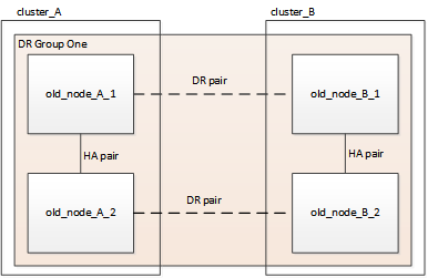
At this stage, the four-node configuration appears as shown in the following image:
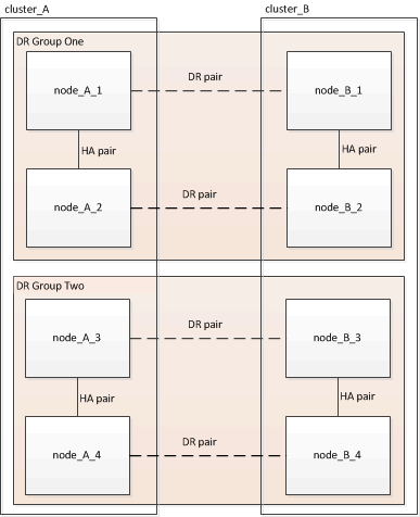
The eight-node configuration appears as shown in the following image:
-
To prevent automatic support case generation, send an AutoSupport message to indicate the upgrade is underway.
-
Issue the following command:
system node autosupport invoke -node * -type all -message "MAINT=10h Upgrading old-model to new-model"The following example specifies a 10 hour maintenance window. Allow additional time depending on your plan.
If the maintenance is completed before the time has elapsed, you can invoke an AutoSupport message indicating the end of the maintenance period:
system node autosupport invoke -node * -type all -message MAINT=end -
Repeat the command on the partner cluster.
-
-
If end-to-end encryption is enabled, follow the steps to Disable end-to-end encryption.
-
Remove the existing MetroCluster configuration from Tiebreaker, Mediator, or other software that can initiate switchover.
If you are using…
Use this procedure…
Tiebreaker
-
Use the Tiebreaker CLI
monitor removecommand to remove the MetroCluster configuration.In the following example, “cluster_A” is removed from the software:
NetApp MetroCluster Tiebreaker :> monitor remove -monitor-name cluster_A
Successfully removed monitor from NetApp MetroCluster Tiebreaker
software.
-
Confirm that the MetroCluster configuration is removed correctly by using the Tiebreaker CLI
monitor show -statuscommand.NetApp MetroCluster Tiebreaker :> monitor show -status
Mediator
Issue the following command from the ONTAP prompt:
metrocluster configuration-settings mediator removeThird-party applications
Refer to the product documentation.
-
-
Perform all of the steps in Expanding a MetroCluster IP configuration to add the new nodes and storage to the configuration.
When the expansion procedure is complete, the temporary configuration appears as shown in the following images:
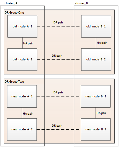 Figure 1. Temporary eight-node configuration
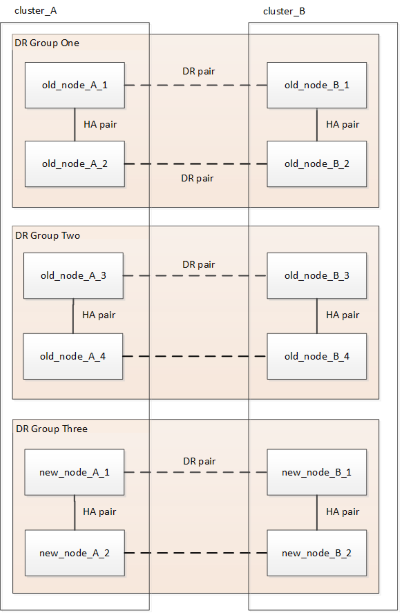 Figure 2. Temporary twelve-node configuration
 -
Confirm that takeover is possible and the nodes are connected by running the following command on both clusters:
storage failover showcluster_A::> storage failover show Takeover Node Partner Possible State Description -------------- -------------------- --------- ------------------ Node_FC_1 Node_FC_2 true Connected to Node_FC_2 Node_FC_2 Node_FC_1 true Connected to Node_FC_1 Node_IP_1 Node_IP_2 true Connected to Node_IP_2 Node_IP_2 Node_IP_1 true Connected to Node_IP_1 -
Move the CRS volumes.
Perform the steps in Moving a metadata volume in MetroCluster configurations.
-
Move the data from the old nodes to the new nodes by using the following procedures:
-
Perform all the steps in Create an aggregate and move volumes to the new nodes.
You might choose to mirror the aggregate when or after it is created. -
Perform all the steps in Move non-SAN data LIFs and cluster-management LIFs to the new nodes.
-
-
Modify the IP address for the cluster peer of the transitioned nodes for each cluster:
-
Identify the cluster_A peer by using the
cluster peer showcommand:cluster_A::> cluster peer show Peer Cluster Name Cluster Serial Number Availability Authentication ------------------------- --------------------- -------------- -------------- cluster_B 1-80-000011 Unavailable absent
-
Modify the cluster_A peer IP address:
cluster peer modify -cluster cluster_A -peer-addrs node_A_3_IP -address-family ipv4
-
-
Identify the cluster_B peer by using the
cluster peer showcommand:cluster_B::> cluster peer show Peer Cluster Name Cluster Serial Number Availability Authentication ------------------------- --------------------- -------------- -------------- cluster_A 1-80-000011 Unavailable absent
-
Modify the cluster_B peer IP address:
cluster peer modify -cluster cluster_B -peer-addrs node_B_3_IP -address-family ipv4
-
-
Verify that the cluster peer IP address is updated for each cluster:
-
Verify that the IP address is updated for each cluster by using the
cluster peer show -instancecommand.The
Remote Intercluster Addressesfield in the following examples displays the updated IP address.Example for cluster_A:
cluster_A::> cluster peer show -instance

Peer Cluster Name: cluster_B
           Remote Intercluster Addresses: 172.21.178.204, 172.21.178.212
      Availability of the Remote Cluster: Available
                     Remote Cluster Name: cluster_B
                     Active IP Addresses: 172.21.178.212, 172.21.178.204
                   Cluster Serial Number: 1-80-000011
                    Remote Cluster Nodes: node_B_3-IP,
                                          node_B_4-IP
                   Remote Cluster Health: true
                 Unreachable Local Nodes: -
          Address Family of Relationship: ipv4
    Authentication Status Administrative: use-authentication
       Authentication Status Operational: ok
                        Last Update Time: 4/20/2023 18:23:53
            IPspace for the Relationship: Default
Proposed Setting for Encryption of Inter-Cluster Communication: -
Encryption Protocol For Inter-Cluster Communication: tls-psk
  Algorithm By Which the PSK Was Derived: jpake

cluster_A::>
Example for cluster_B
cluster_B::> cluster peer show -instance

                       Peer Cluster Name: cluster_A
           Remote Intercluster Addresses: 172.21.178.188, 172.21.178.196 <<<<<<<< Should reflect the modified address
      Availability of the Remote Cluster: Available
                     Remote Cluster Name: cluster_A
                     Active IP Addresses: 172.21.178.196, 172.21.178.188
                   Cluster Serial Number: 1-80-000011
                    Remote Cluster Nodes: node_A_3-IP,
                                          node_A_4-IP
                   Remote Cluster Health: true
                 Unreachable Local Nodes: -
          Address Family of Relationship: ipv4
    Authentication Status Administrative: use-authentication
       Authentication Status Operational: ok
                        Last Update Time: 4/20/2023 18:23:53
            IPspace for the Relationship: Default
Proposed Setting for Encryption of Inter-Cluster Communication: -
Encryption Protocol For Inter-Cluster Communication: tls-psk
  Algorithm By Which the PSK Was Derived: jpake

cluster_B::>
-
-
-
Follow the steps in Removing a Disaster Recovery group to remove the old DR group.
-
If you need to refresh both DR groups in an eight-node configuration, repeat the entire procedure for each DR group.
After you have removed the old DR group, the configuration appears as shown in the following images:
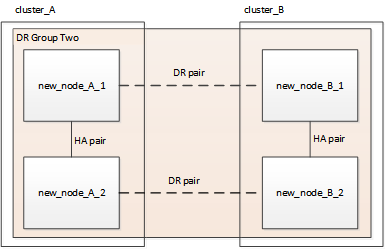 Figure 3. Four-node configuration
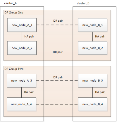 Figure 4. Eight-node configuration
 -
Confirm the operational mode of the MetroCluster configuration and perform a MetroCluster check.
-
Confirm the MetroCluster configuration and that the operational mode is normal:
metrocluster show -
Confirm that all expected nodes are shown:
metrocluster node show -
Issue the following command:
metrocluster check run -
Display the results of the MetroCluster check:
metrocluster check show
-
-
If you disabled end-to-end encryption before adding the new nodes, you can re-enable it by following the steps in Enable end-to-end encryption.
-
Restore monitoring if necessary, using the procedure for your configuration.
If you are using…
Use this procedure
Tiebreaker
Adding MetroCluster configurations in the MetroCluster Tiebreaker Installation and Configuration.
Mediator
Configure ONTAP Mediator from a MetroCluster IP configuration in the MetroCluster IP Installation and Configuration.
Third-party applications
Refer to the product documentation.
-
To resume automatic support case generation, send an Autosupport message to indicate that the maintenance is complete.
-
Issue the following command:
system node autosupport invoke -node * -type all -message MAINT=end -
Repeat the command on the partner cluster.
-


