

Expand a MetroCluster IP configuration
 Suggest changes
Depending on your ONTAP version, you can expand your MetroCluster IP configuration by adding four new nodes as a new DR group.
Beginning with ONTAP 9.13.1, you can temporarily expand an eight-node MetroCluster configuration to refresh the controllers and storage. See Refreshing a four-node or an eight-node MetroCluster IP configuration (ONTAP 9.8 and later) for more information.
Beginning with ONTAP 9.9.1, you can add four new nodes to the MetroCluster IP configuration as a second DR group. This creates an eight-node MetroCluster configuration.
The following guidance is for an uncommon scenario where you need to add an older platform model (platforms released before ONTAP 9.15.1) to an existing MetroCluster configuration that contains a newer platform model (platforms released in ONTAP 9.15.1 or later).
If your existing MetroCluster configuration contains a platform that uses shared cluster/HA ports (platforms released in ONTAP 9.15.1 or later), you cannot add a platform that uses shared MetroCluster/HA ports (platforms released before ONTAP 9.15.1) without upgrading all nodes in the configuration to ONTAP 9.15.1P11 or ONTAP 9.16.1P4 or later.

|
Adding an older platform model that uses shared/MetroCluster HA ports to a MetroCluster containing a newer platform model that uses shared cluster/HA ports is an uncommon scenario and most combinations are not affected. |
Use the following table to verify whether your combination is affected. If your existing platform is listed in the first column, and the platform you want to add to the configuration is listed in the second column, all nodes in the configuration must be running ONTAP 9.15.1P11 or ONTAP 9.16.1P4 or later to add the new DR group.
| If your existing MetroCluster contains.. | And the platform you're adding is… | Then… | ||
|---|---|---|---|---|
An AFF system using shared cluster/HA ports:
|
A FAS system using shared cluster/HA ports:
|
An AFF system using shared MetroCluster/HA ports:
|
A FAS system using shared MetroCluster/HA ports:
|
Before you add the new platform to your existing MetroCluster configuration, upgrade all nodes in the existing and new configuration to ONTAP 9.15.1P11 or ONTAP 9.16.1P4 or later. |
-
The old and new nodes must be running the same version of ONTAP.
-
This procedure describes the steps required to add one four-node DR group to an existing MetroCluster IP configuration. If you are refreshing an eight-node configuration, you must repeat the entire procedure for each DR group, adding one at a time.
-
Verify that the old and new platform models are supported for platform mixing.
-
Verify that the old and new platform models are both supported by the IP switches.
-
If you are refreshing a four-node or an eight-node MetroCluster IP configuration, the new nodes must have enough storage to accommodate the data of the old nodes, along with adequate disks for root aggregates and spare disks.
-
Verify that you have a default broadcast domain created on the old nodes.
When you add new nodes to an existing cluster without a default broadcast domain, node management LIFs are created for the new nodes using universal unique identifiers (UUIDs) instead of the expected names. For more information, see the Knowledge Base article Node management LIFs on newly-added nodes generated with UUID names.
Enable console logging
NetApp strongly recommends that you enable console logging on the devices that you are using and take the following actions when performing this procedure:
-
Leave AutoSupport enabled during maintenance.
-
Trigger a maintenance AutoSupport message before and after maintenance to disable case creation for the duration of the maintenance activity.
See the Knowledge Base article How to suppress automatic case creation during scheduled maintenance windows.
-
Enable session logging for any CLI session. For instructions on how to enable session logging, review the "Logging Session Output" section in the Knowledge Base article How to configure PuTTY for optimal connectivity to ONTAP systems.
Example naming in this procedure
This procedure uses example names throughout to identify the DR groups, nodes, and switches involved.
DR groups |
cluster_A at site_A |
cluster_B at site_B |
|---|---|---|
dr_group_1-old |
|
|
dr_group_2-new |
|
|
Supported platform combinations when adding a second DR group
The following tables shows the supported platform combinations for eight-node MetroCluster IP configurations.

|
|
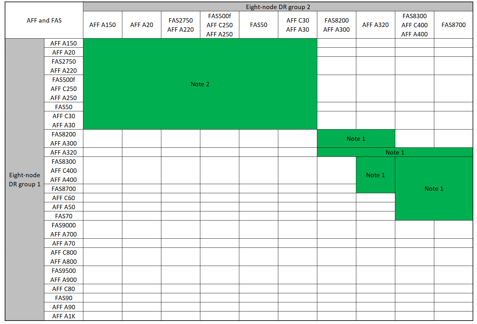
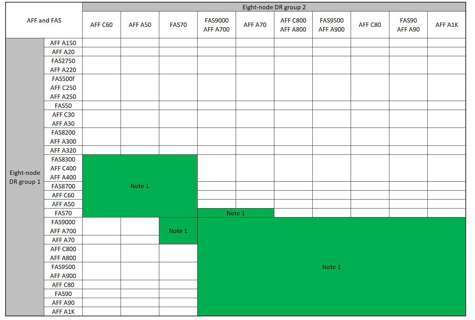
Supported AFF and FAS MetroCluster IP expansion combinations
The following tables show the supported platform combinations for expanding an AFF or FAS system in a MetroCluster IP configuration. The tables are split into two groups:
-
Group 1 shows combinations for AFF A150, AFF A20, FAS2750, AFF A220, FAS500f, AFF C250, AFF A250, FAS50, AFF C30, AFF A30, FAS8200, AFF A300, AFF A320, FAS8300, AFF C400, AFF A400, and FAS8700 systems.
-
Group 2 shows combinations for AFF C60, AFF A50, FAS70, FAS9000, AFF A700, AFF A70, AFF C800, AFF A800, FAS9500, AFF A900, AFF C80, FAS90, AFF A90, and AFF A1K systems.
The following notes apply to both groups:
-
Note 1: ONTAP 9.9.1 or later (or the minimum ONTAP version supported on the platform) is required for these combinations.
-
Note 2: ONTAP 9.13.1 or later (or the minimum ONTAP version supported on the platform) is required for these combinations.
Review the expansion combinations for AFF A150, AFF A20, FAS2750, AFF A220, FAS500f, AFF C250, AFF A250, FAS50, AFF C30, AFF A30, FAS8200, AFF A300, AFF A320, FAS8300, AFF C400, AFF A400, and FAS8700 systems.
Review the expansion combinations for AFF C60, AFF A50, FAS70, FAS9000, AFF A700, AFF A70, AFF C800, AFF A800, FAS9500, AFF A900, AFF C80, FAS90, AFF A90, and AFF A1K systems.
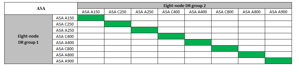
Supported ASA MetroCluster IP expansion combinations
The following table shows the supported platform combinations for expanding an ASA system in a MetroCluster IP configuration:
Send a custom AutoSupport message prior to maintenance
Before performing the maintenance, you should issue an AutoSupport message to notify NetApp technical support that maintenance is underway. Informing technical support that maintenance is underway prevents them from opening a case on the assumption that a disruption has occurred.
This task must be performed on each MetroCluster site.
-
To prevent automatic support case generation, send an Autosupport message to indicate the upgrade is underway.
-
Issue the following command:
system node autosupport invoke -node * -type all -message "MAINT=10h Upgrading <old-model> to <new-model>This example specifies a 10 hour maintenance window. You might want to allow additional time, depending on your plan.
If the maintenance is completed before the time has elapsed, you can invoke an AutoSupport message indicating the end of the maintenance period:
system node autosupport invoke -node * -type all -message MAINT=end -
Repeat the command on the partner cluster.
-
Considerations for VLANs when adding a new DR group
-
The following VLAN considerations apply when expanding a MetroCluster IP configuration:
Certain platforms use a VLAN for the MetroCluster IP interface. By default, each of the two ports use a different VLAN: 10 and 20.
If supported, you can also specify a different (non-default) VLAN higher than 100 (between 101 and 4095) using the
-vlan-idparameter in themetrocluster configuration-settings interface createcommand.The following platforms do not support the
-vlan-idparameter:-
FAS8200 and AFF A300
-
AFF A320
-
FAS9000 and AFF A700
-
AFF C800, ASA C800, AFF A800 and ASA A800
All other platforms support the
-vlan-idparameter.The default and valid VLAN assignments depend on whether the platform supports the
-vlan-idparameter:Platforms that support-vlan-idDefault VLAN:
-
When the
-vlan-idparameter is not specified, the interfaces are created with VLAN 10 for the "A" ports and VLAN 20 for the "B" ports. -
The VLAN specified must match the VLAN selected in the RCF.
Valid VLAN ranges:
-
Default VLAN 10 and 20
-
VLANs 101 and higher (between 101 and 4095)
Platforms that do not support-vlan-idDefault VLAN:
-
Not applicable. The interface does not require a VLAN to be specified on the MetroCluster interface. The switch port defines the VLAN that is used.
Valid VLAN ranges:
-
All VLANs not explicitly excluded when generating the RCF. The RCF alerts you if the VLAN is invalid.
-
-
-
Both DR groups use the same VLANs when you expand from a four-node to an eight-node MetroCluster configuration.
-
If both DR groups cannot be configured using the same VLAN, you must upgrade the DR group that doesn't support the
vlan-idparameter to use a VLAN that is supported by the other DR group.
Verify the health of the MetroCluster configuration
You must verify the health and connectivity of the MetroCluster configuration prior to performing the expansion.
-
Verify the operation of the MetroCluster configuration in ONTAP:
-
Check whether the system is multipathed:
node run -node <node-name> sysconfig -a -
Check for any health alerts on both clusters:
system health alert show -
Confirm the MetroCluster configuration and that the operational mode is normal:
metrocluster show -
Perform a MetroCluster check:
metrocluster check run -
Display the results of the MetroCluster check:
metrocluster check show -
Run Config Advisor.
-
After running Config Advisor, review the tool's output and follow the recommendations in the output to address any issues discovered.
-
-
Verify that the cluster is healthy:
cluster showcluster_A::> cluster show Node Health Eligibility -------------- ------ ----------- node_A_1 true true node_A_2 true true cluster_A::>
-
Verify that all cluster ports are up:
network port show -ipspace Clustercluster_A::> network port show -ipspace Cluster Node: node_A_1-old Speed(Mbps) Health Port IPspace Broadcast Domain Link MTU Admin/Oper Status --------- ------------ ---------------- ---- ---- ----------- -------- e0a Cluster Cluster up 9000 auto/10000 healthy e0b Cluster Cluster up 9000 auto/10000 healthy Node: node_A_2-old Speed(Mbps) Health Port IPspace Broadcast Domain Link MTU Admin/Oper Status --------- ------------ ---------------- ---- ---- ----------- -------- e0a Cluster Cluster up 9000 auto/10000 healthy e0b Cluster Cluster up 9000 auto/10000 healthy 4 entries were displayed. cluster_A::> -
Verify that all cluster LIFs are up and operational:
network interface show -vserver ClusterEach cluster LIF should display true for Is Home and have a Status Admin/Oper of up/up
cluster_A::> network interface show -vserver cluster Logical Status Network Current Current Is Vserver Interface Admin/Oper Address/Mask Node Port Home ----------- ---------- ---------- ------------------ ------------- ------- ----- Cluster node_A_1-old_clus1 up/up 169.254.209.69/16 node_A_1 e0a true node_A_1-old_clus2 up/up 169.254.49.125/16 node_A_1 e0b true node_A_2-old_clus1 up/up 169.254.47.194/16 node_A_2 e0a true node_A_2-old_clus2 up/up 169.254.19.183/16 node_A_2 e0b true 4 entries were displayed. cluster_A::> -
Verify that auto-revert is enabled on all cluster LIFs:
network interface show -vserver Cluster -fields auto-revertcluster_A::> network interface show -vserver Cluster -fields auto-revert Logical Vserver Interface Auto-revert --------- ------------- ------------ Cluster node_A_1-old_clus1 true node_A_1-old_clus2 true node_A_2-old_clus1 true node_A_2-old_clus2 true 4 entries were displayed. cluster_A::>
Remove the configuration from monitoring applications
If the existing configuration is monitored with the MetroCluster Tiebreaker software, the ONTAP Mediator or other third-party applications (for example, ClusterLion) that can initiate a switchover, you must remove the MetroCluster configuration from the monitoring software prior to upgrade.
-
Remove the existing MetroCluster configuration from Tiebreaker, Mediator, or other software that can initiate switchover.
If you are using…
Use this procedure…
Tiebreaker
Mediator
Issue the following command from the ONTAP prompt:
metrocluster configuration-settings mediator removeThird-party applications
Refer to the product documentation.
-
Remove the existing MetroCluster configuration from any third-party application that can initiate switchover.
Refer to the documentation for the application.
Prepare the new controller modules
You must prepare the four new MetroCluster nodes and install the correct ONTAP version.
This task must be performed on each of the new nodes:
-
node_A_3-new
-
node_A_4-new
-
node_B_3-new
-
node_B_4-new
In these steps, you clear the configuration on the nodes and clear the mailbox region on new drives.
-
Rack the new controllers.
-
Cable the new MetroCluster IP nodes to the IP switches as shown in Cable the IP switches.
-
Configure the MetroCluster IP nodes using the following procedures:
-
From Maintenance mode, issue the halt command to exit Maintenance mode:
halt -
Check if the partner-sysid is correct:
printenv partner-sysid -
If the partner-sysid is not correct, set it:
setenv partner-sysid <partner-sysID> -
Boot the system and get to cluster setup:
boot_ontapDo not complete the cluster wizard or node wizard at this time.
Upgrade RCF files
If you are installing new switch firmware, you must install the switch firmware before upgrading the RCF file.
This procedure disrupts traffic on the switch where the RCF file is upgraded. Traffic will resume once the new RCF file is applied.
-
Verify the health of the configuration.
-
Verify that the MetroCluster components are healthy:
metrocluster check runcluster_A::*> metrocluster check run
The operation runs in the background.
-
After the
metrocluster check runoperation completes, runmetrocluster check showto view the results.After approximately five minutes, the following results are displayed:
-----------
::*> metrocluster check show

Component           Result
------------------- ---------
nodes               ok
lifs                ok
config-replication  ok
aggregates          ok
clusters            ok
connections         ok
volumes             ok
7 entries were displayed.
-
Check the status of the running MetroCluster check operation:
metrocluster operation history show -job-id 38 -
Verify that there are no health alerts:
system health alert show
-
-
Prepare the IP switches for the application of the new RCF files.
Follow the steps for your switch vendor:
-
Download and install the IP RCF file, depending on your switch vendor.

Update the switches in the following order: Switch_A_1, Switch_B_1, Switch_A_2, Switch_B_2 -
Download and install the NVIDIA IP RCF files
If you have an L2 shared or L3 network configuration, you might need to adjust the ISL ports on the intermediate/customer switches. The switch port mode might change from 'access' to 'trunk' mode. Only proceed to upgrade the second switch pair (A_2, B_2) if the network connectivity between switches A_1 and B_1 is fully operational and the network is healthy.
Join the new nodes to the clusters
You must add the four new MetroCluster IP nodes to the existing MetroCluster configuration.
You must perform this task on both clusters.
-
Add the new MetroCluster IP nodes to the existing MetroCluster configuration.
-
Join the first new MetroCluster IP node (node_A_1-new) to the existing MetroCluster IP configuration.
Welcome to the cluster setup wizard. You can enter the following commands at any time: "help" or "?" - if you want to have a question clarified, "back" - if you want to change previously answered questions, and "exit" or "quit" - if you want to quit the cluster setup wizard. Any changes you made before quitting will be saved. You can return to cluster setup at any time by typing "cluster setup". To accept a default or omit a question, do not enter a value. This system will send event messages and periodic reports to NetApp Technical Support. To disable this feature, enter autosupport modify -support disable within 24 hours. Enabling AutoSupport can significantly speed problem determination and resolution, should a problem occur on your system. For further information on AutoSupport, see: http://support.netapp.com/autosupport/ Type yes to confirm and continue {yes}: yes Enter the node management interface port [e0M]: 172.17.8.93 172.17.8.93 is not a valid port. The physical port that is connected to the node management network. Examples of node management ports are "e4a" or "e0M". You can type "back", "exit", or "help" at any question. Enter the node management interface port [e0M]: Enter the node management interface IP address: 172.17.8.93 Enter the node management interface netmask: 255.255.254.0 Enter the node management interface default gateway: 172.17.8.1 A node management interface on port e0M with IP address 172.17.8.93 has been created. Use your web browser to complete cluster setup by accessing https://172.17.8.93 Otherwise, press Enter to complete cluster setup using the command line interface: Do you want to create a new cluster or join an existing cluster? {create, join}: join Existing cluster interface configuration found: Port MTU IP Netmask e0c 9000 169.254.148.217 255.255.0.0 e0d 9000 169.254.144.238 255.255.0.0 Do you want to use this configuration? {yes, no} [yes]: yes . . . -
Join the second new MetroCluster IP node (node_A_2-new) to the existing MetroCluster IP configuration.
-
-
Repeat these steps to join node_B_1-new and node_B_2-new to cluster_B.
Configure intercluster LIFs for cluster peering
You must create intercluster LIFs on ports used for communication between the MetroCluster partner clusters. You can use dedicated ports or ports that also have data traffic.
You can configure intercluster LIFs on dedicated ports. Doing so typically increases the available bandwidth for replication traffic.
-
List the ports in the cluster:
network port showFor complete command syntax, see the ONTAP command reference.
The following example shows the network ports in "cluster01":
cluster01::> network port show Speed (Mbps) Node Port IPspace Broadcast Domain Link MTU Admin/Oper ------ --------- ------------ ---------------- ----- ------- ------------ cluster01-01 e0a Cluster Cluster up 1500 auto/1000 e0b Cluster Cluster up 1500 auto/1000 e0c Default Default up 1500 auto/1000 e0d Default Default up 1500 auto/1000 e0e Default Default up 1500 auto/1000 e0f Default Default up 1500 auto/1000 cluster01-02 e0a Cluster Cluster up 1500 auto/1000 e0b Cluster Cluster up 1500 auto/1000 e0c Default Default up 1500 auto/1000 e0d Default Default up 1500 auto/1000 e0e Default Default up 1500 auto/1000 e0f Default Default up 1500 auto/1000 -
Determine which ports are available to dedicate to intercluster communication:
network interface show -fields home-port,curr-portFor complete command syntax, see the ONTAP command reference.
The following example shows that ports "e0e" and "e0f" have not been assigned LIFs:
cluster01::> network interface show -fields home-port,curr-port vserver lif home-port curr-port ------- -------------------- --------- --------- Cluster cluster01-01_clus1 e0a e0a Cluster cluster01-01_clus2 e0b e0b Cluster cluster01-02_clus1 e0a e0a Cluster cluster01-02_clus2 e0b e0b cluster01 cluster_mgmt e0c e0c cluster01 cluster01-01_mgmt1 e0c e0c cluster01 cluster01-02_mgmt1 e0c e0c -
Create a failover group for the dedicated ports:
network interface failover-groups create -vserver <system_svm> -failover-group <failover_group> -targets <physical_or_logical_ports>The following example assigns ports "e0e" and "e0f" to failover group "intercluster01" on SVM "cluster01":
cluster01::> network interface failover-groups create -vserver cluster01 -failover-group
intercluster01 -targets
cluster01-01:e0e,cluster01-01:e0f,cluster01-02:e0e,cluster01-02:e0f
-
Verify that the failover group was created:
network interface failover-groups showFor complete command syntax, see the ONTAP command reference.
cluster01::> network interface failover-groups show Failover Vserver Group Targets ---------------- ---------------- -------------------------------------------- Cluster Cluster cluster01-01:e0a, cluster01-01:e0b, cluster01-02:e0a, cluster01-02:e0b cluster01 Default cluster01-01:e0c, cluster01-01:e0d, cluster01-02:e0c, cluster01-02:e0d, cluster01-01:e0e, cluster01-01:e0f cluster01-02:e0e, cluster01-02:e0f intercluster01 cluster01-01:e0e, cluster01-01:e0f cluster01-02:e0e, cluster01-02:e0f -
Create intercluster LIFs on the system SVM and assign them to the failover group.
network interface create -vserver <system_svm> -lif <lif_name> -service-policy default-intercluster -home-node <node_name> -home-port <port_name> -address <port_ip_address> -netmask <netmask_address> -failover-group <failover_group>The following example creates intercluster LIFs "cluster01_icl01" and "cluster01_icl02" in failover group "intercluster01":
cluster01::> network interface create -vserver cluster01 -lif cluster01_icl01 -service-
policy default-intercluster -home-node cluster01-01 -home-port e0e -address 192.168.1.201
-netmask 255.255.255.0 -failover-group intercluster01

cluster01::> network interface create -vserver cluster01 -lif cluster01_icl02 -service-
policy default-intercluster -home-node cluster01-02 -home-port e0e -address 192.168.1.202
-netmask 255.255.255.0 -failover-group intercluster01
-
Verify that the intercluster LIFs were created:
network interface show -service-policy default-interclustercluster01::> network interface show -service-policy default-intercluster Logical Status Network Current Current Is Vserver Interface Admin/Oper Address/Mask Node Port Home ----------- ---------- ---------- ------------------ ------------- ------- ---- cluster01 cluster01_icl01 up/up 192.168.1.201/24 cluster01-01 e0e true cluster01_icl02 up/up 192.168.1.202/24 cluster01-02 e0e true -
Verify that the intercluster LIFs are redundant:
network interface show -service-policy default-intercluster -failoverThe following example shows that the intercluster LIFs "cluster01_icl01" and "cluster01_icl02" on port "e0e" will fail over to port "e0f".
cluster01::> network interface show -service-policy default-intercluster -failover
         Logical         Home                  Failover        Failover
Vserver  Interface       Node:Port             Policy          Group
-------- --------------- --------------------- --------------- --------
cluster01
         cluster01_icl01 cluster01-01:e0e   local-only      intercluster01
                            Failover Targets:  cluster01-01:e0e,
                                               cluster01-01:e0f
         cluster01_icl02 cluster01-02:e0e   local-only      intercluster01
                            Failover Targets:  cluster01-02:e0e,
                                               cluster01-02:e0f
You can configure intercluster LIFs on ports shared with the data network. Doing so reduces the number of ports you need for intercluster networking.
-
List the ports in the cluster:
network port showFor complete command syntax, see the ONTAP command reference.
The following example shows the network ports in "cluster01":
cluster01::> network port show Speed (Mbps) Node Port IPspace Broadcast Domain Link MTU Admin/Oper ------ --------- ------------ ---------------- ----- ------- ------------ cluster01-01 e0a Cluster Cluster up 1500 auto/1000 e0b Cluster Cluster up 1500 auto/1000 e0c Default Default up 1500 auto/1000 e0d Default Default up 1500 auto/1000 cluster01-02 e0a Cluster Cluster up 1500 auto/1000 e0b Cluster Cluster up 1500 auto/1000 e0c Default Default up 1500 auto/1000 e0d Default Default up 1500 auto/1000 -
Create intercluster LIFs on the system SVM:
network interface create -vserver <system_svm> -lif <lif_name> -service-policy default-intercluster -home-node <node_name> -home-port <port_name> -address <port_ip_address> -netmask <netmask>The following example creates intercluster LIFs "cluster01_icl01" and "cluster01_icl02":
cluster01::> network interface create -vserver cluster01 -lif cluster01_icl01 -service-
policy default-intercluster -home-node cluster01-01 -home-port e0c -address 192.168.1.201
-netmask 255.255.255.0

cluster01::> network interface create -vserver cluster01 -lif cluster01_icl02 -service-
policy default-intercluster -home-node cluster01-02 -home-port e0c -address 192.168.1.202
-netmask 255.255.255.0
-
Verify that the intercluster LIFs were created:
network interface show -service-policy default-interclusterYou should see output like the following example:
cluster01::> network interface show -service-policy default-intercluster Logical Status Network Current Current Is Vserver Interface Admin/Oper Address/Mask Node Port Home ----------- ---------- ---------- ------------------ ------------- ------- ---- cluster01 cluster01_icl01 up/up 192.168.1.201/24 cluster01-01 e0c true cluster01_icl02 up/up 192.168.1.202/24 cluster01-02 e0c true -
Verify that the intercluster LIFs are redundant:
network interface show -service-policy default-intercluster -failoverThe following example shows that intercluster LIFs "cluster01_icl01" and "cluster01_icl02" on the "e0c" port will fail over to the "e0d" port.
cluster01::> network interface show -service-policy default-intercluster -failover
         Logical         Home                  Failover        Failover
Vserver  Interface       Node:Port             Policy          Group
-------- --------------- --------------------- --------------- --------
cluster01
         cluster01_icl01 cluster01-01:e0c   local-only         Default
                            Failover Targets: cluster01-01:e0c,
                                              cluster01-01:e0d
         cluster01_icl02 cluster01-02:e0c   local-only         Default
                            Failover Targets: cluster01-02:e0c,
                                              cluster01-02:e0d
Create the MetroCluster interfaces and mirror root aggregates
You must create the MetroCluster interfaces on the new MetroCluster IP nodes and mirror root aggregates.
-
The home port used in the examples are platform-specific. You should use the home port specific to your MetroCluster IP node platform.
-
Review the information in Considerations for VLANs when adding a new DR group before performing this task.
-
On each site, add the new intercluster LIFs to the peer relationship.
From cluster_A, run the following command:
cluster peer modify -cluster cluster_B -peer-addrs <node_B_1-old IC port_ip_address>,<node_B_2-old IC port_ip_address>,<node_B_1-new IC port_ip_address>,<node_B_2-new IC port_ip_address>From cluster_B, run the following command:
cluster peer modify -cluster cluster_A -peer-addrs <node_A_1-old IC port_ip_address>,<node_A_2-old IC port_ip_address>,<node_A_1-new IC port_ip_address>,<node_A_2-new IC port_ip_address> -
On each site, verify that cluster peering is configured:
cluster peer showThe following example shows the cluster peering configuration on cluster_A:
cluster_A:> cluster peer show
Peer Cluster Name         Cluster Serial Number Availability   Authentication
------------------------- --------------------- -------------- --------------
cluster_B                 1-80-000011           Available      ok
cluster_A::>
The following example shows the cluster peering configuration on cluster_B:
cluster_B:> cluster peer show
Peer Cluster Name         Cluster Serial Number Availability   Authentication
------------------------- --------------------- -------------- --------------
cluster_A                 1-80-000011           Available      ok
cluster_B::>
-
Create the DR group for the MetroCluster IP nodes:
metrocluster configuration-settings dr-group create -partner-clusterFor more information on the MetroCluster configuration settings and connections, see the following:
cluster_A::> metrocluster configuration-settings dr-group create -partner-cluster
cluster_B -local-node node_A_1-new -remote-node node_B_1-new
[Job 259] Job succeeded: DR Group Create is successful.
cluster_A::>
-
Verify that the DR group was created.
metrocluster configuration-settings dr-group showcluster_A::> metrocluster configuration-settings dr-group show DR Group ID Cluster Node DR Partner Node ----------- -------------------------- ------------------ ------------------ 1 cluster_A node_A_1-old node_B_1-old node_A_2-old node_B_2-old cluster_B node_B_1-old node_A_1-old node_B_2-old node_A_2-old 2 cluster_A node_A_1-new node_B_1-new node_A_2-new node_B_2-new cluster_B node_B_1-new node_A_1-new node_B_2-new node_A_2-new 8 entries were displayed. cluster_A::> -
Configure the MetroCluster IP interfaces for the newly joined MetroCluster IP nodes:
-
Do not use 169.254.17.x or 169.254.18.x IP addresses when you create MetroCluster IP interfaces to avoid conflicts with system auto-generated interface IP addresses in the same range.
-
If supported, you can specify a different (non-default) VLAN higher than 100 (between 101 and 4095) using the
-vlan-idparameter in themetrocluster configuration-settings interface createcommand. Refer to Considerations for VLANs when adding a new DR group for supported platform information. -
You can configure the MetroCluster IP interfaces from either cluster.
metrocluster configuration-settings interface create -cluster-namecluster_A::> metrocluster configuration-settings interface create -cluster-name cluster_A -home-node node_A_1-new -home-port e1a -address 172.17.26.10 -netmask 255.255.255.0 [Job 260] Job succeeded: Interface Create is successful. cluster_A::> metrocluster configuration-settings interface create -cluster-name cluster_A -home-node node_A_1-new -home-port e1b -address 172.17.27.10 -netmask 255.255.255.0 [Job 261] Job succeeded: Interface Create is successful. cluster_A::> metrocluster configuration-settings interface create -cluster-name cluster_A -home-node node_A_2-new -home-port e1a -address 172.17.26.11 -netmask 255.255.255.0 [Job 262] Job succeeded: Interface Create is successful. cluster_A::> :metrocluster configuration-settings interface create -cluster-name cluster_A -home-node node_A_2-new -home-port e1b -address 172.17.27.11 -netmask 255.255.255.0 [Job 263] Job succeeded: Interface Create is successful. cluster_A::> metrocluster configuration-settings interface create -cluster-name cluster_B -home-node node_B_1-new -home-port e1a -address 172.17.26.12 -netmask 255.255.255.0 [Job 264] Job succeeded: Interface Create is successful. cluster_A::> metrocluster configuration-settings interface create -cluster-name cluster_B -home-node node_B_1-new -home-port e1b -address 172.17.27.12 -netmask 255.255.255.0 [Job 265] Job succeeded: Interface Create is successful. cluster_A::> metrocluster configuration-settings interface create -cluster-name cluster_B -home-node node_B_2-new -home-port e1a -address 172.17.26.13 -netmask 255.255.255.0 [Job 266] Job succeeded: Interface Create is successful. cluster_A::> metrocluster configuration-settings interface create -cluster-name cluster_B -home-node node_B_2-new -home-port e1b -address 172.17.27.13 -netmask 255.255.255.0 [Job 267] Job succeeded: Interface Create is successful.
-
-
Verify the MetroCluster IP interfaces are created:
metrocluster configuration-settings interface showcluster_A::>metrocluster configuration-settings interface show DR Config Group Cluster Node Network Address Netmask Gateway State ----- ------- ------- --------------- --------------- --------------- --------- 1 cluster_A node_A_1-old Home Port: e1a 172.17.26.10 255.255.255.0 - completed Home Port: e1b 172.17.27.10 255.255.255.0 - completed node_A_2-old Home Port: e1a 172.17.26.11 255.255.255.0 - completed Home Port: e1b 172.17.27.11 255.255.255.0 - completed cluster_B node_B_1-old Home Port: e1a 172.17.26.13 255.255.255.0 - completed Home Port: e1b 172.17.27.13 255.255.255.0 - completed node_B_1-old Home Port: e1a 172.17.26.12 255.255.255.0 - completed Home Port: e1b 172.17.27.12 255.255.255.0 - completed 2 cluster_A node_A_3-new Home Port: e1a 172.17.28.10 255.255.255.0 - completed Home Port: e1b 172.17.29.10 255.255.255.0 - completed node_A_3-new Home Port: e1a 172.17.28.11 255.255.255.0 - completed Home Port: e1b 172.17.29.11 255.255.255.0 - completed cluster_B node_B_3-new Home Port: e1a 172.17.28.13 255.255.255.0 - completed Home Port: e1b 172.17.29.13 255.255.255.0 - completed node_B_3-new Home Port: e1a 172.17.28.12 255.255.255.0 - completed Home Port: e1b 172.17.29.12 255.255.255.0 - completed 8 entries were displayed. cluster_A> -
Connect the MetroCluster IP interfaces:
metrocluster configuration-settings connection connect
This command might take several minutes to complete. cluster_A::> metrocluster configuration-settings connection connect cluster_A::>
-
Verify the connections are properly established:
metrocluster configuration-settings connection show
The output of the metrocluster configuration-settings connection showcommand can vary depending on your platform model. For example, on some platforms, the lines for HA Partner are not displayed in the output.cluster_A::> metrocluster configuration-settings connection show DR Source Destination Group Cluster Node Network Address Network Address Partner Type Config State ----- ------- ------- --------------- --------------- ------------ ------------ 1 cluster_A node_A_1-old Home Port: e1a 172.17.28.10 172.17.28.11 HA Partner completed Home Port: e1a 172.17.28.10 172.17.28.12 DR Partner completed Home Port: e1a 172.17.28.10 172.17.28.13 DR Auxiliary completed Home Port: e1b 172.17.29.10 172.17.29.11 HA Partner completed Home Port: e1b 172.17.29.10 172.17.29.12 DR Partner completed Home Port: e1b 172.17.29.10 172.17.29.13 DR Auxiliary completed node_A_2-old Home Port: e1a 172.17.28.11 172.17.28.10 HA Partner completed Home Port: e1a 172.17.28.11 172.17.28.13 DR Partner completed Home Port: e1a 172.17.28.11 172.17.28.12 DR Auxiliary completed Home Port: e1b 172.17.29.11 172.17.29.10 HA Partner completed Home Port: e1b 172.17.29.11 172.17.29.13 DR Partner completed Home Port: e1b 172.17.29.11 172.17.29.12 DR Auxiliary completed DR Source Destination Group Cluster Node Network Address Network Address Partner Type Config State ----- ------- ------- --------------- --------------- ------------ ------------ 1 cluster_B node_B_2-old Home Port: e1a 172.17.28.13 172.17.28.12 HA Partner completed Home Port: e1a 172.17.28.13 172.17.28.11 DR Partner completed Home Port: e1a 172.17.28.13 172.17.28.10 DR Auxiliary completed Home Port: e1b 172.17.29.13 172.17.29.12 HA Partner completed Home Port: e1b 172.17.29.13 172.17.29.11 DR Partner completed Home Port: e1b 172.17.29.13 172.17.29.10 DR Auxiliary completed node_B_1-old Home Port: e1a 172.17.28.12 172.17.28.13 HA Partner completed Home Port: e1a 172.17.28.12 172.17.28.10 DR Partner completed Home Port: e1a 172.17.28.12 172.17.28.11 DR Auxiliary completed Home Port: e1b 172.17.29.12 172.17.29.13 HA Partner completed Home Port: e1b 172.17.29.12 172.17.29.10 DR Partner completed Home Port: e1b 172.17.29.12 172.17.29.11 DR Auxiliary completed DR Source Destination Group Cluster Node Network Address Network Address Partner Type Config State ----- ------- ------- --------------- --------------- ------------ ------------ 2 cluster_A node_A_1-new** Home Port: e1a 172.17.26.10 172.17.26.11 HA Partner completed Home Port: e1a 172.17.26.10 172.17.26.12 DR Partner completed Home Port: e1a 172.17.26.10 172.17.26.13 DR Auxiliary completed Home Port: e1b 172.17.27.10 172.17.27.11 HA Partner completed Home Port: e1b 172.17.27.10 172.17.27.12 DR Partner completed Home Port: e1b 172.17.27.10 172.17.27.13 DR Auxiliary completed node_A_2-new Home Port: e1a 172.17.26.11 172.17.26.10 HA Partner completed Home Port: e1a 172.17.26.11 172.17.26.13 DR Partner completed Home Port: e1a 172.17.26.11 172.17.26.12 DR Auxiliary completed Home Port: e1b 172.17.27.11 172.17.27.10 HA Partner completed Home Port: e1b 172.17.27.11 172.17.27.13 DR Partner completed Home Port: e1b 172.17.27.11 172.17.27.12 DR Auxiliary completed DR Source Destination Group Cluster Node Network Address Network Address Partner Type Config State ----- ------- ------- --------------- --------------- ------------ ------------ 2 cluster_B node_B_2-new Home Port: e1a 172.17.26.13 172.17.26.12 HA Partner completed Home Port: e1a 172.17.26.13 172.17.26.11 DR Partner completed Home Port: e1a 172.17.26.13 172.17.26.10 DR Auxiliary completed Home Port: e1b 172.17.27.13 172.17.27.12 HA Partner completed Home Port: e1b 172.17.27.13 172.17.27.11 DR Partner completed Home Port: e1b 172.17.27.13 172.17.27.10 DR Auxiliary completed node_B_1-new Home Port: e1a 172.17.26.12 172.17.26.13 HA Partner completed Home Port: e1a 172.17.26.12 172.17.26.10 DR Partner completed Home Port: e1a 172.17.26.12 172.17.26.11 DR Auxiliary completed Home Port: e1b 172.17.27.12 172.17.27.13 HA Partner completed Home Port: e1b 172.17.27.12 172.17.27.10 DR Partner completed Home Port: e1b 172.17.27.12 172.17.27.11 DR Auxiliary completed 48 entries were displayed. cluster_A::> -
Verify disk auto-assignment and partitioning:
disk show -pool Pool1cluster_A::> disk show -pool Pool1 Usable Disk Container Container Disk Size Shelf Bay Type Type Name Owner ---------------- ---------- ----- --- ------- ----------- --------- -------- 1.10.4 - 10 4 SAS remote - node_B_2 1.10.13 - 10 13 SAS remote - node_B_2 1.10.14 - 10 14 SAS remote - node_B_1 1.10.15 - 10 15 SAS remote - node_B_1 1.10.16 - 10 16 SAS remote - node_B_1 1.10.18 - 10 18 SAS remote - node_B_2 ... 2.20.0 546.9GB 20 0 SAS aggregate aggr0_rha1_a1 node_a_1 2.20.3 546.9GB 20 3 SAS aggregate aggr0_rha1_a2 node_a_2 2.20.5 546.9GB 20 5 SAS aggregate rha1_a1_aggr1 node_a_1 2.20.6 546.9GB 20 6 SAS aggregate rha1_a1_aggr1 node_a_1 2.20.7 546.9GB 20 7 SAS aggregate rha1_a2_aggr1 node_a_2 2.20.10 546.9GB 20 10 SAS aggregate rha1_a1_aggr1 node_a_1 ... 43 entries were displayed. cluster_A::> -
Mirror the root aggregates:
storage aggregate mirror -aggregate aggr0_node_A_1-new
You must complete this step on each MetroCluster IP node. cluster_A::> aggr mirror -aggregate aggr0_node_A_1-new Info: Disks would be added to aggregate "aggr0_node_A_1-new"on node "node_A_1-new" in the following manner: Second Plex RAID Group rg0, 3 disks (block checksum, raid_dp) Usable Physical Position Disk Type Size Size ---------- ------------------------- ---------- -------- -------- dparity 4.20.0 SAS - - parity 4.20.3 SAS - - data 4.20.1 SAS 546.9GB 558.9GB Aggregate capacity available forvolume use would be 467.6GB. Do you want to continue? {y|n}: y cluster_A::> -
Verify that the root aggregates are mirrored:
storage aggregate showcluster_A::> aggr show Aggregate Size Available Used% State #Vols Nodes RAID Status --------- -------- --------- ----- ------- ------ ---------------- ------------ aggr0_node_A_1-old 349.0GB 16.84GB 95% online 1 node_A_1-old raid_dp, mirrored, normal aggr0_node_A_2-old 349.0GB 16.84GB 95% online 1 node_A_2-old raid_dp, mirrored, normal aggr0_node_A_1-new 467.6GB 22.63GB 95% online 1 node_A_1-new raid_dp, mirrored, normal aggr0_node_A_2-new 467.6GB 22.62GB 95% online 1 node_A_2-new raid_dp, mirrored, normal aggr_data_a1 1.02TB 1.01TB 1% online 1 node_A_1-old raid_dp, mirrored, normal aggr_data_a2 1.02TB 1.01TB 1% online 1 node_A_2-old raid_dp, mirrored,
Finalize the addition of the new nodes
You must incorporate the new DR group into the MetroCluster configuration and create mirrored data aggregates on the new nodes.
-
Refresh the MetroCluster configuration:
-
Enter advanced privilege mode:
set -privilege advanced -
Refresh the MetroCluster configuration on any of the newly added nodes:
If your MetroCluster configuration has…
Then do this…
Multiple data aggregates
From any node's prompt, run:
metrocluster configure <node-name>A single mirrored data aggregate at one or both sites
From any node's prompt, configure the MetroCluster with the
-allow-with-one-aggregate trueparameter:metrocluster configure -allow-with-one-aggregate true <node-name> -
Reboot each of the new nodes:
node reboot -node <node_name> -inhibit-takeover true
You don't need to reboot the nodes in a specific order, but you should wait until one node is fully booted and all connections are established before rebooting the next node. -
Return to admin privilege mode:
set -privilege admin
-
-
Create mirrored data aggregates on each of the new MetroCluster nodes:
storage aggregate create -aggregate <aggregate-name> -node <node-name> -diskcount <no-of-disks> -mirror true
-
You must create at least one mirrored data aggregate per site. It is recommended to have two mirrored data aggregates per site on MetroCluster IP nodes to host the MDV volumes, however a single aggregate per site is supported (but not recommended). It is acceptable that one site of the MetroCluster has a single mirrored data aggregate and the other site has more than one mirrored data aggregate.
-
Aggregate names must be unique across the MetroCluster sites. This means that you cannot have two different aggregates with the same name on site A and site B.
The following example shows the creation of an aggregate on node_A_1-new.
cluster_A::> storage aggregate create -aggregate data_a3 -node node_A_1-new -diskcount 10 -mirror t Info: The layout for aggregate "data_a3" on node "node_A_1-new" would be: First Plex RAID Group rg0, 5 disks (block checksum, raid_dp) Usable Physical Position Disk Type Size Size ---------- ------------------------- ---------- -------- -------- dparity 5.10.15 SAS - - parity 5.10.16 SAS - - data 5.10.17 SAS 546.9GB 547.1GB data 5.10.18 SAS 546.9GB 558.9GB data 5.10.19 SAS 546.9GB 558.9GB Second Plex RAID Group rg0, 5 disks (block checksum, raid_dp) Usable Physical Position Disk Type Size Size ---------- ------------------------- ---------- -------- -------- dparity 4.20.17 SAS - - parity 4.20.14 SAS - - data 4.20.18 SAS 546.9GB 547.1GB data 4.20.19 SAS 546.9GB 547.1GB data 4.20.16 SAS 546.9GB 547.1GB Aggregate capacity available for volume use would be 1.37TB. Do you want to continue? {y|n}: y [Job 440] Job succeeded: DONE cluster_A::> -
-
Verify that the nodes are added to their DR group.
cluster_A::*> metrocluster node show DR Configuration DR Group Cluster Node State Mirroring Mode ----- ------- ------------------ -------------- --------- -------------------- 1 cluster_A node_A_1-old configured enabled normal node_A_2-old configured enabled normal cluster_B node_B_1-old configured enabled normal node_B_2-old configured enabled normal 2 cluster_A node_A_3-new configured enabled normal node_A_4-new configured enabled normal cluster_B node_B_3-new configured enabled normal node_B_4-new configured enabled normal 8 entries were displayed. cluster_A::*> -
Move the MDV_CRS volumes in advanced privilege mode.
-
Display the volumes to identify the MDV volumes:
If you have a single mirrored data aggregate per site then move both the MDV volumes to this single aggregate. If you have two or more mirrored data aggregates, then move each MDV volume to a different aggregate.
If you are expanding a four-node MetroCluster configuration to a permanent eight-node configuration, you should move one of the MDV volumes to the new DR group.
The following example shows the MDV volumes in the
volume showoutput:cluster_A::> volume show Vserver Volume Aggregate State Type Size Available Used% --------- ------------ ------------ ---------- ---- ---------- ---------- ----- ... cluster_A MDV_CRS_2c78e009ff5611e9b0f300a0985ef8c4_A aggr_b1 - RW - - - cluster_A MDV_CRS_2c78e009ff5611e9b0f300a0985ef8c4_B aggr_b2 - RW - - - cluster_A MDV_CRS_d6b0b313ff5611e9837100a098544e51_A aggr_a1 online RW 10GB 9.50GB 0% cluster_A MDV_CRS_d6b0b313ff5611e9837100a098544e51_B aggr_a2 online RW 10GB 9.50GB 0% ... 11 entries were displayed.mple -
Set the advanced privilege level:
set -privilege advanced -
Move the MDV volumes, one at a time:
volume move start -volume <mdv-volume> -destination-aggregate <aggr-on-new-node> -vserver <svm-name>The following example shows the command and output for moving "MDV_CRS_d6b0b313ff5611e9837100a098544e51_A" to aggregate "data_a3" on "node_A_3".
cluster_A::*> vol move start -volume MDV_CRS_d6b0b313ff5611e9837100a098544e51_A -destination-aggregate data_a3 -vserver cluster_A Warning: You are about to modify the system volume "MDV_CRS_d6b0b313ff5611e9837100a098544e51_A". This might cause severe performance or stability problems. Do not proceed unless directed to do so by support. Do you want to proceed? {y|n}: y [Job 494] Job is queued: Move "MDV_CRS_d6b0b313ff5611e9837100a098544e51_A" in Vserver "cluster_A" to aggregate "data_a3". Use the "volume move show -vserver cluster_A -volume MDV_CRS_d6b0b313ff5611e9837100a098544e51_A" command to view the status of this operation. -
Use the volume show command to check that the MDV volume has been successfully moved:
volume show <mdv-name>The following output shows that the MDV volume has been successfully moved.
cluster_A::*> vol show MDV_CRS_d6b0b313ff5611e9837100a098544e51_B
Vserver     Volume       Aggregate    State      Type       Size  Available Used%
---------   ------------ ------------ ---------- ---- ---------- ---------- -----
cluster_A   MDV_CRS_d6b0b313ff5611e9837100a098544e51_B
                       aggr_a2      online     RW         10GB     9.50GB    0%
-
-
Move epsilon from an old node to a new node:
-
Identify which node currently has epsilon:
cluster show -fields epsiloncluster_B::*> cluster show -fields epsilon node epsilon ---------------- ------- node_A_1-old true node_A_2-old false node_A_3-new false node_A_4-new false 4 entries were displayed.
-
Set epsilon to false on the old node (node_A_1-old):
cluster modify -node <old-node> -epsilon false* -
Set epsilon to true on the new node (node_A_3-new):
cluster modify -node <new-node> -epsilon true -
Verify that epsilon has moved to the correct node:
cluster show -fields epsiloncluster_A::*> cluster show -fields epsilon node epsilon ---------------- ------- node_A_1-old false node_A_2-old false node_A_3-new true node_A_4-new false 4 entries were displayed.
-
-
If your system supports end-to-end encryption, you can Enable end-to-end encryption on the new DR group.