

Replace the boot media - AFF C250
 Suggest changes
To replace the boot media, you must remove the impaired controller module, install the replacement boot media, and transfer the boot image to a USB flash drive.
Step 1: Remove the controller module
To access components inside the controller module, you must first remove the controller module from the system, and then remove the cover on the controller module.
-
If you are not already grounded, properly ground yourself.
-
Unplug the controller module power supplies from the source.
-
Release the power cable retainers, and then unplug the cables from the power supplies.
-
Unplug the I/O cables from the controller module.
-
Insert your forefinger into the latching mechanism on either side of the controller module, press the lever with your thumb, and gently pull the controller a few inches out of the chassis.

If you have difficulty removing the controller module, place your index fingers through the finger holes from the inside (by crossing your arms). 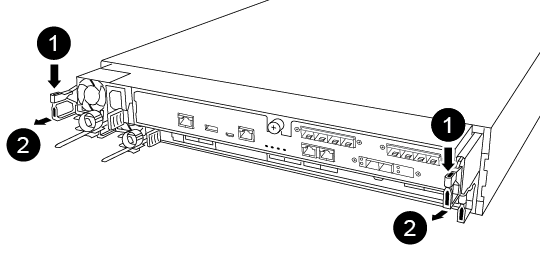

Lever

Latching mechanism
-
Using both hands, grasp the controller module sides and gently pull it out of the chassis and set it on a flat, stable surface.
-
Turn the thumbscrew on the front of the controller module anti-clockwise and open the controller module cover.
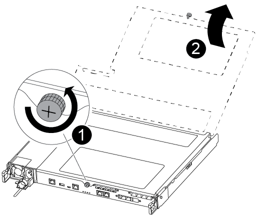
Thumbscrew
Controller module cover.
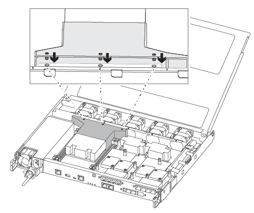
-
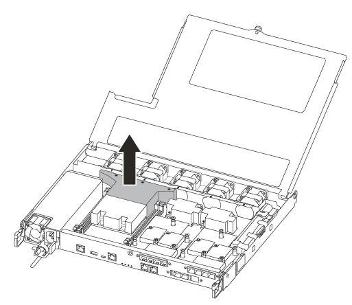
Lift out the air duct cover.
Step 2: Replace the boot media
You locate the failed boot media in the controller module by removing the air duct on the controller module before you can replace the boot media.
You need a #1 magnetic Phillips head screwdriver to remove the screw that holds the boot media in place. Due to the space constraints within the controller module, you should also have a magnet to transfer the screw on to so that you do not lose it.
You can use the following video or the tabulated steps to replace the boot media:
-
Locate and replace the impaired boot media from the controller module.
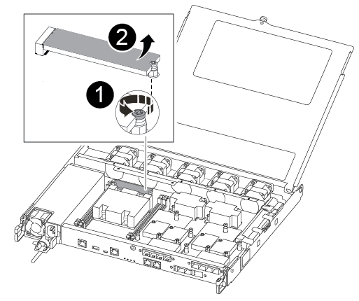
Remove the screw securing the boot media to the motherboard in the controller module.
Lift the boot media out of the controller module.
-
Using the #1 magnetic screwdriver, remove the screw from the impaired boot media, and set it aside safely on the magnet.
-
Gently lift the impaired boot media directly out of the socket and set it aside.
-
Remove the replacement boot media from the antistatic shipping bag and align it into place on the controller module.
-
Using the #1 magnetic screwdriver, insert and tighten the screw on the boot media.
Do not apply force when tightening the screw on the boot media; you might crack it.
Step 3: Transfer the boot image to the boot media
The replacement boot media that you installed is without a boot image so you need to transfer a boot image using a USB flash drive.
-
You must have a USB flash drive, formatted to MBR/FAT32, with at least 4GB capacity
-
A copy of the same image version of ONTAP as what the impaired controller was running. You can download the appropriate image from the Downloads section on the NetApp Support Site
-
If NVE is enabled, download the image with NetApp Volume Encryption, as indicated in the download button.
-
If NVE is not enabled, download the image without NetApp Volume Encryption, as indicated in the download button.
-
-
If your system is an HA pair, you must have a network connection.
-
If your system is a stand-alone system you do not need a network connection, but you must perform an additional reboot when restoring the var file system.
-
Download and copy the appropriate service image from the NetApp Support Site to the USB flash drive.
-
Download the service image to your work space on your laptop.
-
Unzip the service image.
If you are extracting the contents using Windows, do not use winzip to extract the netboot image. Use another extraction tool, such as 7-Zip or WinRAR. There are two folders in the unzipped service image file:
-
boot
-
efi
-
-
Copy the efi folder to the top directory on the USB flash drive.
If the service image has no efi folder, see EFI folder missing from Service Image download file used for boot device recovery for FAS and AFF models^ . The USB flash drive should have the efi folder and the same Service Image (BIOS) version of what the impaired controller is running.
-
Remove the USB flash drive from your laptop.
-
If you have not already done so, install the air duct.
-
Close the controller module cover and tighten the thumbscrew.
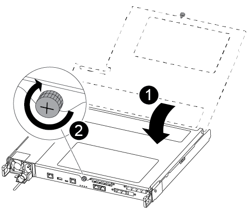
Controller module cover
Thumbscrew
-
Align the end of the controller module with the opening in the chassis, and then gently push the controller module halfway into the system.
-
Insert the USB flash drive into the USB slot on the controller module.
Make sure that you install the USB flash drive in the slot labeled for USB devices, and not in the USB console port.
-
Push the controller module all the way into the chassis:
-
Place your index fingers through the finger holes from the inside of the latching mechanism.
-
Press your thumbs down on the orange tabs on top of the latching mechanism and gently push the controller module over the stop.
-
Release your thumbs from the top of the latching mechanisms and continue pushing until the latching mechanisms snap into place.
The controller module should be fully inserted and flush with the edges of the chassis.
-
Reconnect the controller module I/O cables.
-
Plug the power cords into the power supplies, reinstall the power cable locking collar, and then connect the power supplies to the power source.
The controller module begins to boot as soon as power is restored. Be prepared to interrupt the boot process.
-
Interrupt the boot process to stop at the LOADER prompt by pressing Ctrl-C when you see Starting AUTOBOOT press Ctrl-C to abort….
If you miss this message, press Ctrl-C, select the option to boot to Maintenance mode, and then halt the controller to boot to LOADER.
-
For systems with one controller in the chassis, reconnect the power and turn on the power supplies.
The system begins to boot and stops at the LOADER prompt.
-